Memory Model
Overview of Memory Model
Memory Attributes
The Kunminghu V2R2 supports three types of memory: cacheable memory, non-cacheable memory, and non-cacheable peripheral.
The physical memory attributes (Physical Memory Attributes) of an address are defined by hardware and support the attributes specified in the RISC-V manual:
- R (Read Permission): Read permission
- W (Write Permission): Write permission
- X (Execute Permission): Execution permission
- A (Address matching mode): Address matching mode
- L (Lock Bit): Lock status
Additionally, Kunminghu V2R2 supports the atomic (supporting atomic instructions) and c (supporting cache) attributes.
Memory Consistency Model
The cacheable memory adopts the RVWMO (RISC-V Weak Memory Ordering) memory model. Under this model, the actual read/write order of memory among multiple cores may not match the program-specified access sequence. Therefore, the RISC-V instruction set architecture provides Fence instructions to ensure memory access synchronization. Additionally, the RISC-V A extension includes LR/SC instructions and AMO instructions for locking and atomic operations.
Both non-cacheable memory and non-cacheable peripheral memory types are strongly ordered.
Virtual memory management
MMU Overview
The Kunminghu V2R2 MMU (Memory Management Unit) supports RISC-V SV48 and SV39 paging mechanisms. Its main functions include:
- Address translation: Converts virtual addresses (48 or 39 bits) to physical addresses (48 bits);
- Page protection: Checks the read/write/execute permissions of the page's accessors.
- Virtualization support: Enables two-stage address translation in a virtualized environment to convert guest virtual addresses to host physical addresses.
- Exception handling: Each module returns exceptions based on the request source.
TLB Organization
The MMU primarily utilizes the TLB (Translation Look-aside Buffer) to implement functions such as address translation. The TLB takes multiple virtual addresses used by the CPU for memory access as input, checks the page attributes in the TLB before conversion, and then outputs the physical address corresponding to the virtual address.
The Kunminghu V2R2 MMU employs a two-level TLB structure, with the first level being L1 TLB, consisting of instruction ITLB and data DTLB, and the second level being L2 TLB.
The configuration of L1 ITLB entries is as follows in the table.
| Item name | item count | **Organization structure ** | Replacement Algorithm | stored content |
|---|---|---|---|---|
| Page | 48 | Fully associative | PLRU | All size pages |
The configuration of L1 DTLB entries is as follows in the table
| Item name | item count | **Organization structure ** | Replacement Algorithm | stored content |
|---|---|---|---|---|
| Page | 48 | Fully associative | PLRU | All size pages |
For instruction fetch requests, load and store requests, when accessing the ITLB and DTLB, if a hit occurs, the physical address and corresponding permission attributes can be obtained in the next cycle.
The L2 TLB is shared by instructions and data, and the L2 TLB consists of six main units:
- Page Cache: Caches page tables. All four levels of the Sv48 page table are cached separately, enabling single-cycle querying of all four levels of information. Additionally, for virtualization requests, the Page Cache separately stores first-stage (va -> gpa) and second-stage (gpa -> hpa) requests, without directly storing va -> hpa mappings.
- Page Table Walker: Queries the first two levels of page tables in memory;
- Last Level Page Table Walker: Queries the last-level page table in memory;
- Hypervisor Page Table Walker: Responsible for querying the second-stage page table translation.
- Miss Queue: Handles miss requests from cache queries to Page Cache and Last Level Page Walker.
- Prefetcher: A prefetch unit.
Address translation process
The MMU is responsible for translating virtual addresses into physical addresses and uses the translated physical addresses for memory access. Kunminghu V2R2 supports Sv39/Sv48 paging mechanisms, with virtual address lengths of 39/48 bits. The lower 12 bits are page offsets. For Sv39, the upper 27 bits are divided into three segments (9 bits each), forming a three-level page table. For Sv48, the upper 36 bits are divided into four segments (9 bits each), forming a four-level page table.
The physical address of Kunminghu V2R2 is 48 bits, with the structure of virtual and physical addresses as shown in the diagram. Traversing the page table requires four memory accesses, necessitating the use of TLB to cache the page table.



During address translation, instruction fetch at the frontend uses ITLB for address translation, while memory access at the backend uses DTLB. If ITLB or DTLB misses, a request is sent to L2 TLB via Repeater. Both frontend instruction fetch and backend memory access employ non-blocking TLB access. If TLB returns a miss, other requests can be rescheduled for query.
The page table of Kunminghu V2R2 is used to store the entry addresses of lower-level page tables or the physical information of final page tables. The page table structure is shown in Figure 6.3:

Kunminghu V2R2 Page Table Structure Bit Attributes:
PBMT: Page-Based Memory Types
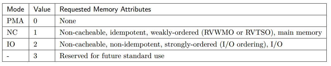
The PBMT bit indicates the PMA attributes of the virtual address, with specific definitions scenario-dependent, as illustrated. (Note: This feature requires enabling the PBMTE bit in the menvcfg register.)
- PMA mode maintains compatibility with the original system attribute settings when virtual address PMA was undefined, adhering to the original physical address PMA attributes, i.e., the sysmap attributes;
- In NC mode, forcibly override non-cacheable, idempotent, and weakly ordered attributes, typically used for main memory;
- In IO mode, forcibly override non-cacheable, non-idempotent, and strongly ordered attributes, typically used for peripherals;
- When the PBMT bit is 3, it indicates a reserved mode, to be defined in the future.
- For PMA attributes not covered by SVPBMT, the original physical address's PMA takes precedence. For attributes that are forcibly overridden, PBMT takes precedence.
RSW: Reserved for use by Supervisor softWare
Reserved page table attribute bits for privileged software, not processed by hardware.
**D: Dirty bit: ** indicates whether the page has been written to since the D bit was last cleared.
A: Access bit: indicates whether the page has been accessed (including memory access and instruction fetch) since the A bit was last cleared.
**G: Global bit: ** indicates the page applies globally.
U: User bit: Indicates the page is dedicated to User mode.
X: Executable bit: indicates the page is executable.
**W: Writeable bit: ** indicates the page is writable.
**R: Readable bit: ** indicates the page is readable.
**V: Valid bit: ** indicates the page is valid.
Kunminghu V2R2 supports the Svade extension. If a page is accessed (for memory access or instruction fetch) without the A bit set, or written to without the D bit set, a page fault will be triggered. It does not support the Svadu extension and will not update the A/D bits in hardware.
The detailed process of address translation is described below, using Sv39 as an example:
When the CPU accesses a virtual address, if the TLB hits, the physical address and related attributes are directly obtained from the TLB. If the TLB misses, the specific steps for address translation are as follows:
- Obtain the L1 page table memory access address {SATP.PPN, VPN[2], 3’b0} based on SATP.PPN and VPN[2], then use this address to access the L2 Cache and retrieve the 64-bit L1 page table PTE;
- Check if the PTE complies with PMP permissions. If not, generate the corresponding access fault exception; if compliant, determine whether the X/W/R bits meet the leaf page table conditions based on the rules. If they meet the leaf page table conditions, it indicates that the final physical address has been found, proceed to Step 3; if not, return to Step 1, replace satp.ppn with pte.ppn, change vpn to the next-level vpn, concatenate with 3'b0, and continue the first step process;
- Found the leaf page table, combined with the X/W/R/L bits in PMP and the X/W/R bits in PTE to obtain the minimum permissions for permission checking, and backfilled the PTE content into the L2 TLB.
- At any step of the PMP check, if there is a permission violation, generate the corresponding access fault exception based on the access type;
- If a leaf page table is obtained but: the access type violates the settings of A/D/X/W/R/U bits, a corresponding page fault exception is generated; if no leaf page table is obtained after three accesses, a corresponding page fault exception is generated; if an access fault response is received during the L2 Cache access, a page fault exception is generated.
- If a leaf page table is obtained but the number of accesses is fewer than 3, it indicates a large page table has been obtained. Check if the PPN of the large page table is aligned according to the page table size; if not aligned, a page fault exception is generated.
Additional note: Kunminghu V2R2 does not allow access to page tables built in MMIO address spaces. If during page table traversal, an address of a certain level page table is found to be within MMIO space, an access fault exception will be raised.
Two-stage address translation for virtualization
Kunminghu V2R2 supports the H extension. In non-virtualization mode and when not executing virtualized memory access instructions, the address translation process is largely consistent with that before the H extension was added. In virtualization mode or when executing virtualized memory access instructions, it is necessary to determine whether two-stage address translation is enabled.
The CPU enables two-stage translation based on vsatp and hgatp. The structure of vsatp is shown in the following figure (SXLEN is fixed at 64 in Kunminghu V2R2)

vsatp controls VS-stage translation. By default, vsatp remains enabled, meaning VS-stage address translation is automatically activated during virtualization mode or when executing virtualized memory access instructions.
hgatp controls G-stage translation. The structure of hgatp and its translation mode are shown in the following diagram:
| ** bit ** | field | Description |
|---|---|---|
| [63:60] | MODE | Indicates the address translation mode. When this field is 0, it is Bare mode, with no address translation or protection enabled. When the field is 8/9, it represents Sv39x4/Sv48x4 address translation modes. Any other value will trigger an illegal instruction fault. |
| [57:44] | VMID | Virtual machine identifier. For the Sv39x4/Sv48x4 address translation modes adopted by Kunminghu V2R2, the maximum VMID length is 14 |
| [43:0] | PPN | Indicates the physical page number of the root page table for the second-stage translation, obtained by right-shifting the physical address by 12 bits. |
Kunminghu V2R2 employs the Sv39x4/Sv48x4 paging mechanism, with the virtual address structures of both mechanisms illustrated below.


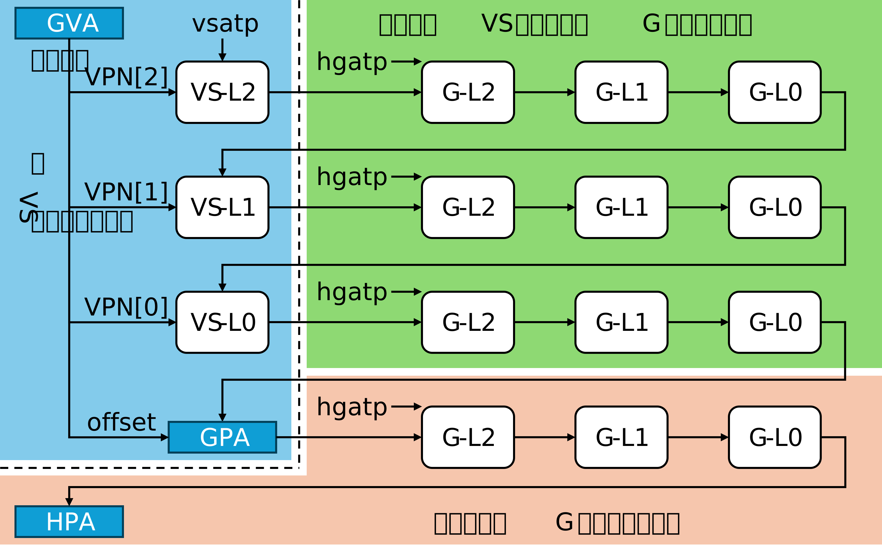
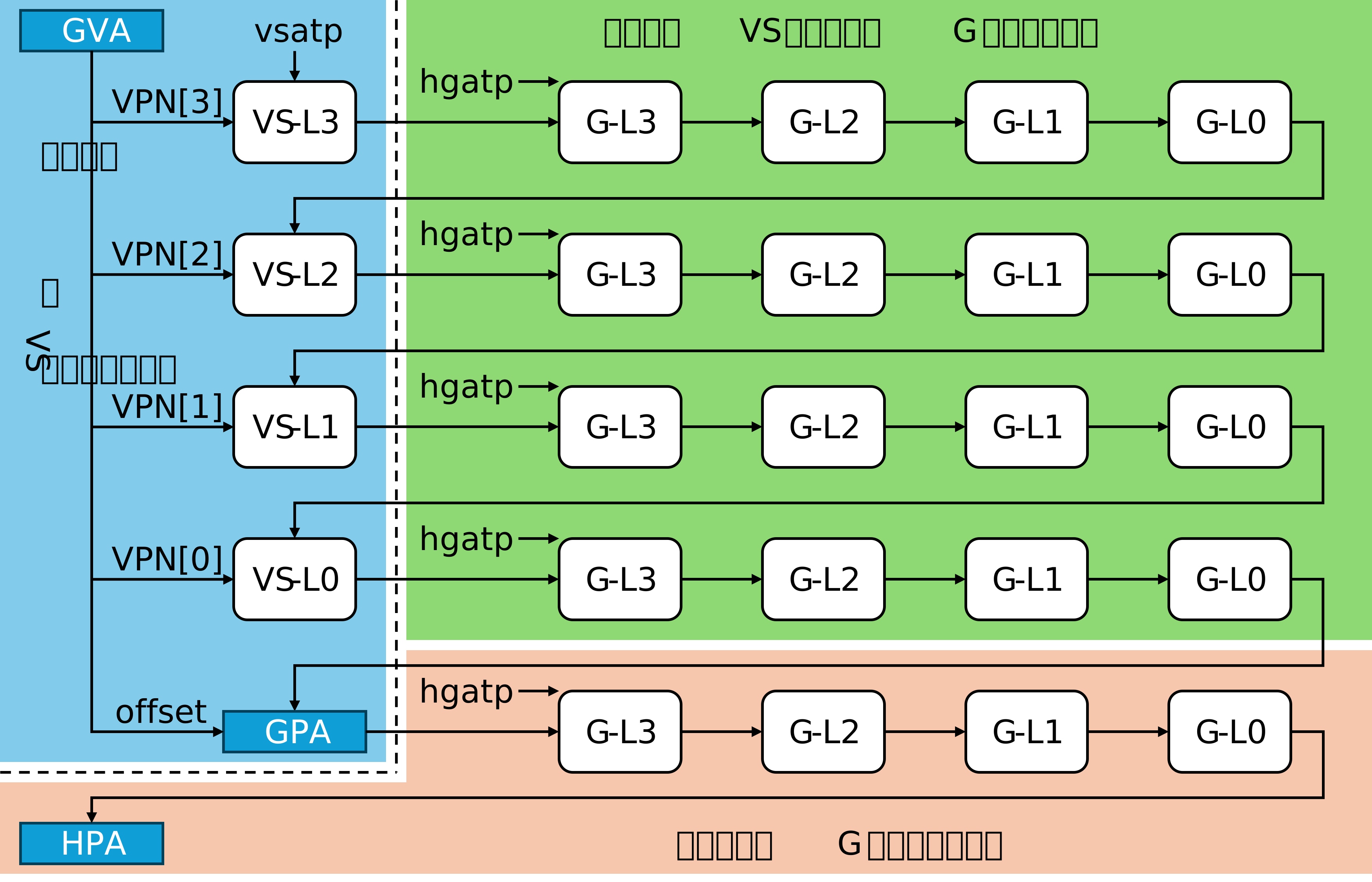
The VS-stage is responsible for translating guest virtual addresses into guest physical addresses, while the G-stage translates guest physical addresses into host physical addresses. The first-stage translation is essentially the same as non-virtualized translation. The second-stage translation is performed in the PTW and LLPTW modules, with the lookup logic as follows: first, search in the Page Cache; if found, return to PTW or LLPTW; if not found, proceed to HPTW for translation, which then returns and populates the Page Cache.
In two-stage address translation, the addresses obtained from the first stage of translation (including the page table addresses calculated during the translation process) are all guest physical addresses. These must undergo a second stage of translation to obtain the actual physical addresses before memory access can proceed to read the page tables. The logical translation processes for Sv39x4 and Sv48x4 are illustrated in the figure below.
System Control Register
MMU Address Translation Register (SATP)
The Kunminghu V2R2 architecture supports an ASID (Address Space Identifier) with a length of 16, stored in the SATP register. The format of the SATP register is shown in the table.
| ** bit ** | field | Description |
|---|---|---|
| [63:60] | MODE | Indicates the address translation mode. When this field is 0, it is Bare mode, with no address translation or protection enabled. When the field is 8/9, it represents Sv39/Sv48 address translation modes. Any other value will trigger an illegal instruction fault. |
| [59:44] | ASID | Address Space Identifier. The length of ASID is configurable via parameters. For the Sv39/Sv48 address translation modes adopted by Kunminghu V2R2, the maximum ASID length is 16. |
| [43:0] | PPN | Represents the physical page number of the root page table, obtained by right-shifting the physical address by 12 bits. |
In virtualization mode, SATP is replaced by the VSATP register, and the PPN within it represents the guest physical page number of the guest root page table rather than the actual physical address, requiring second-stage translation to obtain the real physical address.
Physical memory protection & physical address attributes
PMP Overview
Kunminghu V2R2 complies with the RISC-V standard. The PMP (Physical Memory Protection) unit verifies access permissions for physical addresses, determining whether the CPU has read/write/execute privileges for the address in the current operating mode.
The PMA (Physical Memory Attributes) unit defines the attributes of physical memory. It primarily specifies memory region types, defines memory access characteristics, and controls memory access behavior.
PMA works in conjunction with PMP to jointly manage and control physical memory access and attributes, ensuring system security and performance.
The design specifications of the Kunminghu V2R2 PMP&PMA unit include:
- Supports physical address protection;
- Support for physical address attributes;
- Supports parallel execution checks for PMP & PMA;
- Supports distributed PMP and distributed PMA;
- Supports exception handling.
PMP Control Register
The Kunminghu V2R2 defaults to 16 PMP entries, which can be modified through parameterization, employing a distributed replication implementation method. Each PMP entry primarily consists of an 8-bit configuration register and a 64-bit address register, with no default initial values.
The address space of PMP registers is as follows in the table
| PMP register name | address |
|---|---|
| pmpcfg0 | 0x3A0 |
| pmpcfg2 | 0x3A2 |
| pmpaddr0 | 0x3B0 |
| pmpaddr1 | 0x3B1 |
| pmpaddr2 | 0x3B2 |
| pmpaddr3 | 0x3B3 |
| pmpaddr4 | 0x3B4 |
| pmpaddr5 | 0x3B5 |
| pmpaddr6 | 0x3B6 |
| pmpaddr7 | 0x3B7 |
| pmpaddr8 | 0x3B8 |
| pmpaddr9 | 0x3B9 |
| pmpaddr10 | 0x3BA |
| pmpaddr11 | 0x3BB |
| pmpaddr12 | 0x3BC |
| pmpaddr13 | 0x3BD |
| pmpaddr14 | 0x3BE |
| pmpaddr15 | 0x3BF |
Among them, the layout of PMP configuration registers pmpcfg0 and pmpcfg2 is as shown in the figure.

The format of the PMP configuration register is as shown in the table below.
| ** bit ** | field | Description |
|---|---|---|
| 7 | L | Indicates whether the PMP entry is locked. This field defaults to 0, meaning unlocked; when set to 1, it indicates locked and requires a reset to unlock. |
| [6:5] | Reserved | Reserved bits, default to 0 |
| [4:3] | A | Indicates the address matching mode of this PMP entry. The default value is 0, meaning the PMP entry is disabled and does not match any address. Values 1, 2, and 3 represent TOR, NA4, and NAPOT address matching modes, respectively. |
| 2 | X | Indicates whether the address configured in this PMP entry supports instruction execution. A value of 1 indicates execution support, while 0 indicates no execution support. |
| 1 | W | Indicates whether the address configured in this PMP entry supports write operations. A value of 1 indicates write support, while 0 indicates no write support. |
| 0 | R | Indicates whether the address configured in this PMP entry supports read operations. A value of 1 means read is supported, while 0 means read is not supported. |
The format of the PMP address register is shown in the following table.
| ** bit ** | field | Description |
|---|---|---|
| [63:34] | 0 | The upper 30 bits of the PMP address register are 0 |
| [33:0] | address | Stores bits [35:2] of the PMP entry configuration address. |
PMA Attribute Register
The implementation of PMA adopts a method similar to PMP. PMA registers have default initial values and must be manually configured to match the platform's address attributes. PMA registers utilize the reserved CSR address space in M-mode, defaulting to 16 entries.
The address space of PMA registers is shown in the following table
| PMA register name | address | reset value |
|---|---|---|
| pmacfg0 | 0x7C0 | 64'h80b080d08000000 |
| pmacfg2 | 0x7C2 | 64'h6f0b080b080f080b |
| pmaaddr0 | 0x7C8 | 64'h0 |
| pmaaddr1 | 0x7C9 | 64'h0 |
| pmaaddr2 | 0x7CA | 64'h0 |
| pmaaddr3 | 0x7CB | 64'h4000000 |
| pmaaddr4 | 0x7CC | 64'h8000000 |
| pmaaddr5 | 0x7CD | 64'hc000000 |
| pmaaddr6 | 0x7CE | 64'hc4c4000 |
| pmaaddr7 | 0x7CF | 64'he000000 |
| pmaaddr8 | 0x7D0 | 64'he004000 |
| pmaaddr9 | 0x7D1 | 64'he008000 |
| pmaaddr10 | 0x7D2 | 64'he008400 |
| pmaaddr11 | 0x7D3 | 64'he400000 |
| pmaaddr12 | 0x7D4 | 64'he400800 |
| pmaaddr13 | 0x7D5 | 64'hf000000 |
| pmaaddr14 | 0x7D6 | 64'h20000000 |
| pmaaddr15 | 0x7D7 | 64'h120000000 |
The layout of pmacfg0 and pmacfg2 is as shown in the figure.

The format of PMA configuration registers is shown in the following table
| ** bit ** | field | Description |
|---|---|---|
| 7 | L | Indicates whether the PMA entry is locked. This field defaults to 0, meaning unlocked; when set to 1, it indicates locked. |
| 6 | C | Indicates whether the address configured in this PMA entry is cacheable. A value of 1 means it is cacheable, while 0 means the address belongs to MMIO space and is not cacheable. |
| 5 | Atomic | Indicates whether the address configured in this PMA entry allows atomic access. A value of 1 means atomic access is permitted, and 0 means atomic access is not permitted. |
| [4:3] | A | Indicates the address matching mode of this PMA entry. This field defaults to 0, meaning the PMA entry is disabled and does not match any address. When this field is 1, 2, or 3, it represents TOR, NA4, or NAPOT address matching modes respectively. |
| 2 | X | Indicates whether the address configured in this PMA entry supports instruction execution. When this field is 1, it supports instruction execution; when 0, it does not. |
| 1 | W | Indicates whether the address configured in this PMA entry supports write operations. A value of 1 means write is supported, and 0 means write is not supported. |
| 0 | R | Indicates whether the address configured by this PMA entry supports read operations. A value of 1 indicates read support, while 0 indicates no read support. |
The format of the PMA address register is shown in the table below.
| ** bit ** | field | Description |
|---|---|---|
| [63:34] | 0 | The upper 30 bits of the PMA address register are 0 |
| [33:0] | address | Stores bits [35:2] of the address for PMA entry configuration |
The address space and attributes described by the PMA registers are shown in the following table:
| Lower address bound | Upper Address Bound | Description | attribute |
|---|---|---|---|
| 0x00_0000_0000 | 0x00_0FFF_FFFF | Reserved | |
| 0x00_1000_0000 | 0x00_1FFF_FFFF | QSPI Flash | RX |
| 0x00_2000_0000 | 0x00_2FFF_FFFF | Reserved | |
| 0x00_3000_0000 | 0x00_3000_FFFF | GPU(V550) | RW |
| 0x00_3001_0000 | 0x00_3001_FFFF | G71 | RW |
| 0x00_3002_0000 | 0x00_3003_FFFF | Reserved | |
| 0x00_3004_0000 | 0x00_3004_FFFF | DMA | RW |
| 0x00_3005_0000 | 0x00_3005_FFFF | SDMMC | RW |
| 0x00_3006_0000 | 0x00_3015_FFFF | USB | RW |
| 0x00_3016_0000 | 0x00_3025_FFFF | DATA_CPU_BRIDGE | RW |
| 0x00_3026_0000 | 0x00_30FF_FFFF | Reserved | |
| 0x00_3100_0000 | 0x00_3100_FFFF | QSPI | RW |
| 0x00_3101_0000 | 0x00_3101_FFFF | GMAC | RW |
| 0x00_3102_0000 | 0x00_3102_FFFF | HDMI | RW |
| 0x00_3103_0000 | 0x00_3103_FFFF | HDMI_PHY | RW |
| 0x00_3104_0000 | 0x00_3105_FFFF | DP | RW |
| 0x00_3106_0000 | 0x00_3106_FFFF | DDR0 | RW |
| 0x00_3107_0000 | 0x00_3107_FFFF | DDR0_PHY | RW |
| 0x00_3108_0000 | 0x00_3108_FFFF | DDR1 | RW |
| 0x00_3109_0000 | 0x00_3109_FFFF | DDR1_PHY | RW |
| 0x00_310A_0000 | 0x00_310A_FFFF | IIS | RW |
| 0x00_310B_0000 | 0x00_310B_FFFF | UART0 | RW |
| 0x00_310C_0000 | 0x00_310C_FFFF | UART1 | RW |
| 0x00_310D_0000 | 0x00_310D_FFFF | UART2 | RW |
| 0x00_310E_0000 | 0x00_310E_FFFF | IIC0 | RW |
| 0x00_310F_0000 | 0x00_310F_FFFF | IIC1 | RW |
| 0x00_3110_0000 | 0x00_3110_FFFF | IIC2 | RW |
| 0x00_3111_0000 | 0x00_3111_FFFF | GPIO | RW |
| 0x00_3112_0000 | 0x00_3112_FFFF | CRU | RW |
| 0x00_3113_0000 | 0x00_3113_FFFF | WDT | RW |
| 0x00_3114_0000 | 0x00_3114_FFFF | USB2_PHY0 | RW |
| 0x00_3115_0000 | 0x00_3115_FFFF | USB2_PHY1 | RW |
| 0x00_3116_0000 | 0x00_3116_FFFF | USB2_PHY2 | RW |
| 0x00_3117_0000 | 0x00_3117_FFFF | USB2_PHY3 | RW |
| 0x00_3118_0000 | 0x00_3118_FFFF | USB3_PHY0 | RW |
| 0x00_3119_0000 | 0x00_3119_FFFF | USB3_PHY1 | RW |
| 0x00_311a_0000 | 0x00_311a_FFFF | USB3_PHY2 | RW |
| 0x00_311b_0000 | 0x00_311b_FFFF | USB3_PHY3 | RW |
| 0x00_311c_0000 | 0x00_311c_FFFF | PCIE0_CFG | RW |
| 0x00_311d_0000 | 0x00_311d_FFFF | PCIE1_CFG | RW |
| 0x00_311e_0000 | 0x00_311e_FFFF | PCIE2_CFG | RW |
| 0x00_311f_0000 | 0x00_311f_FFFF | PCIE3_CFG | RW |
| 0x00_3120_0000 | 0x00_3120_FFFF | SYSCFG | RW |
| 0x00_3121_0000 | 0x00_3130_FFFF | DATA_CPU_BRIDGE | RW |
| 0x00_3131_0000 | 0x00_37FF_FFFF | Reserved | |
| 0x00_3800_0000 | 0x00_3800_FFFF | CLINT (In CPU) | RW |
| 0x00_3801_0000 | 0x00_3801_FFFF | Reserved | |
| 0x00_3802_0000 | 0x00_3802_0FFF | Debug (In CPU) | RW |
| 0x00_3802_1000 | 0x00_38FF_FFFF | Reserved | |
| 0x00_3900_0000 | 0x00_3900_0FFF | CacheCtrl | RW |
| 0x00_3900_1000 | 0x00_3900_1FFF | Core Reset | RW |
| 0x00_3900_2000 | 0x00_3BFF_FFFF | Reserved | |
| 0x00_3C00_0000 | 0x00_3FFF_FFFF | PLIC (In CPU) | RW |
| 0x00_4000_0000 | 0x00_4FFF_FFFF | PCIe0 | RW |
| 0x00_5000_0000 | 0x00_5FFF_FFFF | PCIe1 | RW |
| 0x00_6000_0000 | 0x00_6FFF_FFFF | PCIe2 | RW |
| 0x00_7000_0000 | 0x00_7FFF_FFFF | PCIe3 | RW |
| 0x00_8000_0000 | 0x1F_FFFF_FFFF | DDR | RWXIDSA |
The entry information of the PMA registers is shown in the following table
| address | c | atomic | a | x | w | r |
|---|---|---|---|---|---|---|
| 0x0 | false | false | 0 | false | false | false |
| 0x0 | false | false | 0 | false | false | false |
| 0x0 | false | false | 0 | false | false | false |
| 0x10000000 | false | false | 1 | false | false | false |
| 0x20000000 | false | false | 1 | true | false | true |
| 0x30000000 | false | false | 1 | false | false | false |
| 0x31310000 | false | false | 1 | false | true | true |
| 0x38000000 | false | false | 1 | false | false | false |
| 0x38010000 | false | false | 1 | false | true | true |
| 0x38020000 | false | false | 1 | false | false | false |
| 0x38021000 | false | false | 1 | true | true | true |
| 0x39000000 | false | false | 1 | false | false | false |
| 0x39002000 | false | false | 1 | false | true | true |
| 0x3c000000 | false | false | 1 | false | false | false |
| 0x80000000 | false | false | 1 | false | true | true |
| 0x480000000 | true | true | 1 | true | true | true |
Exception Handling Mechanism
The Kunminghu V2R2 MMU module may generate 4 types of exceptions, including guest page fault, page fault, access fault, and ECC check errors in the L2 TLB page cache. These are handled by corresponding modules based on the request source.
The possible exceptions generated by MMU and their handling procedures are listed in the following table
| module | Possible Exceptions | ** processing flow ** |
|---|---|---|
| ITLB | ||
| Generate inst page fault | Deliver to Icache or IFU for processing based on request source | |
| Generate inst guest page fault | Deliver to Icache or IFU for processing based on request source | |
| Generate inst access fault | Deliver to Icache or IFU for processing based on request source | |
| DTLB | ||
| Generates a load page fault | Hand over to LoadUnits for processing. | |
| Generate load guest page fault | Hand over to LoadUnits for processing. | |
| Generate store page fault | Based on the request source, it is processed by StoreUnits or AtomicsUnit respectively | |
| Generate store guest page fault | Based on the request source, it is dispatched to either StoreUnits or AtomicsUnit for processing. | |
| Generate a load access fault | Hand over to LoadUnits for processing. | |
| Generate store access fault | Based on the request source, it is processed by StoreUnits or AtomicsUnit respectively | |
| L2 TLB | ||
| Generate guest page fault | Delivered to L1 TLB, which processes the request based on its origin | |
| Generate page fault | Delivered to L1 TLB, which processes the request based on its origin | |
| Generate access fault | Delivered to L1 TLB, which processes the request based on its origin | |
| ECC check error | Invalidate the current entry, return a miss result, and restart Page Walk. |
Additionally, according to the RISC-V manual, Page Fault has higher priority than Access Fault. However, if an Access Fault occurs during Page Table Walk due to PMP or PMA checks, making the page table entry invalid, a special case arises where both Page Fault and Access Fault occur simultaneously. In such cases, Kunminghu V2R2 chooses to report the Access Fault. In all other scenarios, Page Fault maintains higher priority over Access Fault.
Memory access sequence
In different scenarios, Kunminghu V2R2 has different processes for accessing address spaces, which can be briefly summarized as follows:
Scenario 1: CPU does not perform VA-PA translation
- The CPU needs to access PA;
- Look up address attributes;
- PMP check, verify address read, write, and execute permissions;
- Perform address access.
Scenario 2: VA-PA translation in non-virtualized environment
- CPU attempts to access VA;
- Perform address translation via MMU to obtain the page table entry;
- Look up address, attributes, and permission information based on PTE;
- PMP check, verify address read, write, and execute permissions;
- Perform address access.
Scenario 3: VA-PA translation in a virtualized environment
- The CPU needs to access guest VA;
- Check virtualization registers to confirm whether two-stage address translation is enabled.
- The MMU performs two-stage address translation to obtain the page table entry;
- Look up address, attributes, and permission information based on PTE;
- PMP check, verify address read, write, and execute permissions;
- Perform address access.