Kunming Lake IFU Module Documentation
- Version: V2R2
- Status: OK
- Date: 2025/01/03
- commit: 7d889d887f665295eec9cdb987e037e008f875a6
Glossary of Terms
| Abbreviation | Full name | Description |
|---|---|---|
| CRU | Clock Reset Unit | Clock reset unit. |
| RVC | RISC-V Compressed Instructions | 16-bit compressed instructions as defined by the RISC-V "C" extension |
| RVI | RISC-V Integer Instructions | 32-bit base integer instructions as specified in the RISC-V manual |
| IFU | Instruction Fetch Unit | Instruction Fetch Unit |
| FTQ | Fetch Target Queue. | Fetch Target Queue |
| PreDecode | Predecoder Module | Pre-decoder |
| PredChecker | Prediction Check Module | Branch Prediction Result Checker |
| ICache | L1 Instruction Cache | Level-1 Instruction Cache |
| IBuffer | Instruction Buffer | Instruction Buffer |
| CFI | Control Flow Instruction | Control Flow Instruction |
| PC | Program Counter | Program Counter |
| ITLB | Instruction Translation Lookaside Buffer | Instruction Address Translation Lookaside Buffer |
| InstrUncache | Instruction Ucache Module | Instruction MMIO Fetch Handling Unit |
Submodule List
| Submodule | Description |
|---|---|
| PreDecoder | Pre-decode Module |
| InstrUncache | Instruction MMIO Fetch Handling Unit |
Functional Description
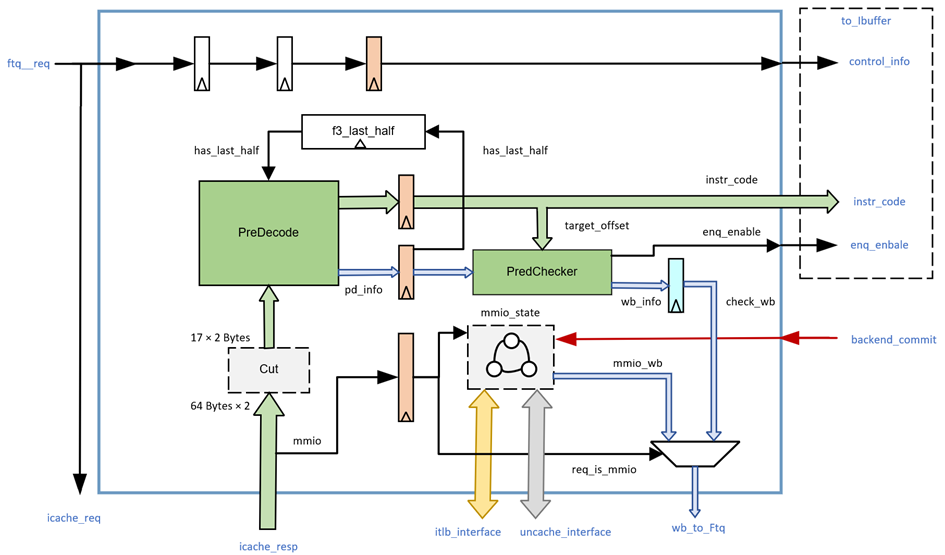
The FTQ sends predicted block requests to both the ICache and IFU modules. The IFU waits for up to two cache lines of instruction codes returned from the ICache, then splits them to generate initial instruction codes within the fetch request range. These are sent to the pre-decoder for pre-decoding. In the next cycle, the valid instruction range is adjusted based on pre-decoding information, and the instruction codes are expanded along with other information before being sent to the IBuffer module. When the ICache detects that the address belongs to MMIO space, the IFU sends the address to the MMIO processing unit for instruction fetch. At this point, the processor enters a multi-cycle sequential execution mode, and the IFU stalls the pipeline until it receives a commit signal from the ROB, allowing the next instruction fetch request to proceed. Additionally, the IFU handles special cases for 32-bit instructions spanning MMIO address pages (retransmission mechanism).
Accept FTQ instruction fetch requests
The IFU receives fetch requests from the FTQ in prediction block units, including the prediction block start address, the next cacheline start address of the current cacheline, the start address of the next prediction block, the queue pointer of the prediction block in the FTQ, whether the prediction block contains a taken CFI instruction and its position within the block, as well as control signals (whether the request is valid and if the IFU is ready). Each prediction block can contain up to 32 bytes of instruction code, with a maximum of 16 instructions.
Dual cacheline instruction fetch
If and only if the fetch address of a prediction block falls in the latter half of a cacheline, to meet the requirement of a maximum 34-byte prediction block, the IFU will fetch two consecutive cachelines from the ICache, generating exception information (page fault and access fault) for each, and split them as described in Feature 3.
After June 2024, the ICache implemented a low-power design, handling data selection and concatenation internally. Thus, the IFU no longer needs to manage how two cacheline data are concatenated and selected. It simply copies and concatenates the data returned by the ICache for segmentation. Please refer to ICache documentation.
You may also refer to the comments in IFU.scala.
Instruction Splitting to Generate Initial Instruction Codes
In the next pipeline stage (F1), the PC for every 2 bytes within the predicted block and other relevant information are calculated. The process then proceeds to the F2 stage to await the instruction code from the ICache. At F2, it is necessary to verify whether the instruction code returned by the ICache matches the current pipeline stage (since the IFU pipeline may be flushed while the ICache remains unaffected). Exception information (page fault and access fault) for each instruction is generated based on the cache line exception information returned by the ICache. Concurrently, the jump_range (the instruction range from the start address to the first branch address in the predicted block) and ftr_range (the instruction range from the start address to the next predicted block's start address in the absence of a branch) are calculated using the taken information from the FTQ. For timing considerations, the two ports of the ICache return cache lines for both miss and hit scenarios, resulting in four cache lines that need to generate four combinations (two from port 0 and two from port 1) for parallel pre-decoding. F2 simultaneously selects 17×2-byte initial instruction codes from the 64-byte returned data (of which 40 bytes are valid) based on the predicted block's start address and sends them to four PreDecode modules for pre-decoding.
Generate predecode information
The PreDecode module receives the 17 initial 2-byte instruction codes segmented by F2. On one hand, it pre-decodes these initial instruction codes according to the decoding table to obtain pre-decoding information, including whether the instruction is the start of a valid instruction, whether it is an RVC instruction, whether it is a CFI instruction, the CFI instruction type (branch/JAL/JALR/call/ret), and the target address calculation offset for CFI instructions. The encoding of the brType field in the output pre-decoding information is as follows:
Table 1.2 CFI Instruction Type Encoding
| CFI Instruction Type | Type Encoding (brType) |
|---|---|
| Non-CFI instruction | 00 |
| branch instruction | 01 |
| jal instruction | 10 |
| jalr instruction | 11 |
Generate instruction code and instruction code extension
While generating pre-decoding information, the initial instructions are grouped into 4-byte units (starting from the initial address, with 2-byte address increments, and the first 4 bytes at the address forming a 32-bit initial instruction code) to produce the instruction code for each instruction.
In the next cycle (F3) after generating the instruction code and pre-decode information, the instruction codes of the 16 instructions are sent to 16 instruction expanders for 32-bit instruction expansion (RVC instructions are expanded according to the manual specifications, while RVI instructions retain their original codes).
Branch Prediction Overriding Flushes the Pipeline
When the FTQ does not cache enough prediction blocks, the IFU may directly use the predicted address provided by a simple branch predictor for instruction fetching. In this case, if the precise predictor detects an error in the simple predictor, it must notify the IFU to cancel the ongoing fetch request. Specifically: \ - If the BPU's S2 pipeline stage detects an error, the IFU's F0 stage must be flushed. \ - If the BPU's S3 pipeline stage detects an error, the IFU's F0/F1 stages must be flushed (the BPU's simple predictor provides results in S1 and performs overriding by S3 at the latest, so the IFU's F2/F3 stages are guaranteed to have the best prediction and do not require flushing; similarly, there is no BPU S2 to IFU F1 flushing).
When the IFU receives a flush request from the BPU, it compares the pointer of the fetch request in the F0F1 pipeline stage with the pointer from the BPU's flush request. If the flush pointer precedes the fetch pointer, it indicates that the current fetch request is on an incorrect execution path, necessitating a pipeline flush. Otherwise, the IFU can ignore this flush request from the BPU.
Early branch prediction error check
To reduce flushes caused by easily identifiable branch prediction errors, the IFU performs frontend branch prediction error checks at the F3 pipeline stage using pre-decode information generated by F2. The pre-decode information is first sent to the PredChecker module, which checks for jal-type errors, ret-type errors, invalid instruction prediction errors, and non-CFI instruction prediction errors based on the CFI instruction type. It also calculates 16 branch target addresses from the instruction code and compares them with the predicted target addresses to check for target address errors. The PredChecker corrects jal-type and ret-type prediction errors and regenerates the instruction valid range vector fixedRange (where 1 indicates the instruction is within the prediction block). fixedRange narrows down the range from jump_range and ftr_range based on jal and ret check results, limiting it to the start address up to any undetected jal or ret instructions. Below are the types of branch prediction errors checked by the PredChecker module:
- JAL type error: The predicted block contains a JAL instruction, but the predictor did not predict a branch for this instruction.
- ret type error: There is a ret instruction within the prediction block's range, but the predictor did not predict a jump for this instruction.
- Invalid instruction misprediction: The predictor made a prediction for an invalid instruction (outside the predicted block range or in the middle of a 32-bit instruction).
- Non-CFI instruction misprediction: The predictor mispredicts a valid but non-CFI instruction.
- Branch Target Address Error: The predictor provided an incorrect branch target address.
Frontend Redirect
If the F3 branch prediction check reveals any of the five prediction errors described in Feature 7, the IFU will generate a frontend redirect in the next cycle, flushing all pipeline stages except F3. The FTQ and predictor flushes will be handled by the FTQ after the IFU writes back to the FTQ.
Send Instruction Codes and Frontend Instruction Information to IBuffer
The F3 pipeline stage ultimately obtains the expanded 32-bit instruction code, along with exception information, pre-decoding information, FTQ pointers, and other backend-required data (such as folded PC) for each of the 16 instructions. In addition to the conventional valid-ready control signals, the IFU provides two special signals to the IBuffer: one is the 16-bit io_toIbuffer_bits_valid, indicating valid instructions within the predicted block (1 marks the start of an instruction, while 0 indicates the middle of an instruction). The other is the 16-bit io_toIbuffer_bits_enqEnable, which is derived by ANDing io_toIbuffer_bits_valid with the corrected instruction range fixedRange of the predicted block. An enqEnable value of 1 signifies that this 2-byte instruction code is both the start of an instruction and within the instruction range represented by the predicted block.
Instruction information and misprediction information writeback to FTQ
In the WB stage following F3, the IFU writes back to the FTQ the instruction PC, pre-decoding information, mispredicted instruction positions, correct jump addresses, and the correct instruction range of the prediction block, while passing the FTQ pointer of the prediction block to distinguish between different requests.
Cross-prediction block 32-bit instruction handling
Due to the limited length of predicted blocks, there may be cases where the two bytes of an RVI instruction span across two predicted blocks. The IFU first checks whether the last 2 bytes of the initial predicted block mark the start of an RVI instruction. If so and there is no branch in this predicted block, a flag register f3_lastHalf_valid is set to inform the subsequent predicted block that it contains the latter half of the instruction. During F2 pre-decoding, two distinct instruction valid vectors are generated:
- The start of a prediction block is also the start of an instruction. Based on whether subsequent instructions are RVC or RVI, the instruction valid vector is generated in this manner.
- The prediction block's start address is in the middle of an RVI instruction, generating a valid vector with the instruction starting at start address + 2.
In F3, the final instruction valid vector is determined based on whether there is a cross-prediction block RVI flag. If f3_lastHalf_valid is high, the latter is selected (i.e., the first 2 bytes of this prediction block are not the start of an instruction). As described in Feature 2 earlier, if and only if the start address is in the latter half of the cacheline, two cachelines will be fetched from the ICache. Therefore, even if this cross-prediction block RVI instruction spans cachelines, each prediction block can obtain its complete instruction code. The IFU's processing simply counts this instruction in the first prediction block while invalidating the 2-byte at the start address position of the second prediction block by modifying the instruction valid vector.
MMIO instruction fetch
During processor power-on reset, since memory initialization is not yet complete, the processor needs to fetch instructions from flash storage for execution. In this case, the IFU must send 64-bit requests to the MMIO bus to fetch instructions from the flash address space. Additionally, the IFU prohibits speculative execution on the MMIO bus, meaning the IFU must wait for each instruction to complete execution and obtain the accurate next instruction address before sending the next request to the bus.
After the processor powers on or resets, it fetches instructions starting from address 0x10000000. The ICache translates the address through ITLB to obtain the physical address, which is then checked by PMP to determine if it belongs to MMIO space. The result is returned to the IFU F2 pipeline stage (refer to the ICache documentation). If the instruction fetch request is for MMIO address space, the IFU blocks the request at F3 and a state machine controls the MMIO instruction fetch, as shown in the following diagram:

- The state machine defaults to the
m_idlestate. If the F3 pipeline stage is an MMIO instruction fetch request and no exceptions have occurred previously, the state machine transitions to them_waitLastCmtstate. - (
m_waitLastCmt) The IFU queries the FTQ via the mmioCommitRead port to check if all instructions prior to the IF3 prediction block have been committed. If not, it stalls until all preceding instructions are committed1. - (
m_sendReq) sends the request to the InstrUncache module, issuing a request to the MMIO bus. - (
m_waitResp) After the InstrUncache module returns, the instruction code is extracted from the 64-bit data based on the PC. - If the lower bits of the pc are
3'b110, due to the MMIO bus bandwidth limitation of 8B and alignment requirements, the upper 2B of this request will not contain valid data. If the returned instruction data indicates the instruction is not RVC, this situation requires a resend at pc+2 (aligned to the next 8B boundary) to fetch the complete 4B instruction code. - Before resending, ITLB address translation and PMP checks must be
reperformed for pc+2 (as it may cross a page boundary) (
m_sendTLB,m_TLBResp,m_sendPMP). If ITLB or PMP raises an exception (access fault, page fault, guest page fault) or checks reveal pc+2 is not in MMIO address space, the exception information is sent directly to the backend without fetching. - If no exceptions occur, (
m_resendReq,m_waitResendResp) follows steps 2/3 to issue a request to InstrUncache and receive the instruction code. - When the IFU registers the complete instruction code or encounters an error
(ITLB/PMP error during retry, or corrupt returned by the Uncache module's
tilelink bus), (
m_waitCommit) it can send the instruction data and exception information to the IBuffer. Note that MMIO instruction fetches can only non-speculatively request one instruction at a time from the bus, so only one instruction's data can be sent to the IBuffer. It must then wait for the instruction to commit. - If this instruction is a CFI instruction, it is sent by the backend to initiate a flush to the FTQ.
- For sequential instructions, the IFU reuses the frontend redirection path to flush the pipeline and leverages the FTQ writeback mechanism, treating it as a mispredicted instruction for flushing, redirecting to the instruction address +2 or +4 (depending on whether the instruction is RVI or RVC). This mechanism ensures that only one instruction is fetched from MMIO at a time.
- After commit (
m_commited), the state machine resets tom_idleand clears all registers.
Apart from power-on, the debug extension and Svpbmt extension may also cause the processor to jump to an MMIO address space for instruction fetch at any time during operation. Refer to the RISC-V manual. The handling of MMIO instruction fetch in these cases is identical.
Trigger implements hardware breakpoint functionality for the PC.
There are a total of 4 Triggers in the IFU's FrontendTrigger module, numbered
0-3. The configuration information (breakpoint type, matching address, etc.) for
each Trigger is stored in the tdata registers.
When software writes specific values to the CSR registers tselect and
tdata1/2, the CSR sends a tUpdate request to the IFU to update the
configuration information in the tdata registers of FrontendTrigger.
Currently, frontend Triggers can only be configured as PC breakpoints
(mcontrol.select register is 0; when mcontrol.select=1, the Trigger will
never hit and will not generate an exception).
During instruction fetch, the IFU's F3 pipeline stage queries the
FrontendTrigger module and receives results in the same cycle. The latter checks
each instruction in the fetch block against every Trigger. When not in debug
mode, if the instruction's PC and the content of the tdata2 register satisfy
the relationship indicated by the mcontrol.match bits (Xiangshan supports
mcontrol.match bits 0, 2, and 3, corresponding to equal, greater than, and
less than), the instruction is marked as a Trigger hit. This triggers a
breakpoint exception in the backend during execution, entering M-Mode or debug
mode. The frontend Trigger supports the Chain function. When their corresponding
mcontrol.chain bit is set, an exception is only generated if both the current
Trigger and the next numbered Trigger hit simultaneously2.
Overall design
Overall block diagram and pipeline stages

Interface timing
FTQ Request Interface Timing Example
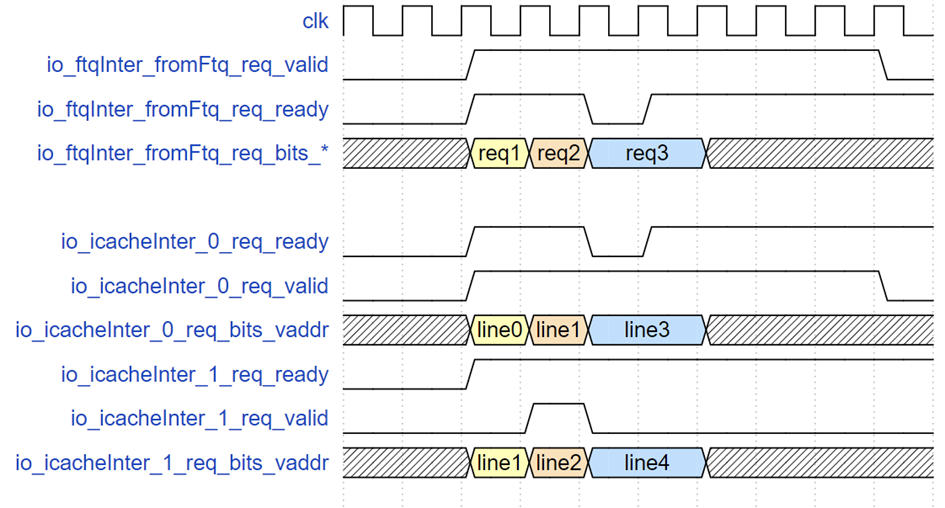
The diagram above illustrates three FTQ request examples: req1 only requests cacheline line0, followed by req2 requesting line1 and line2. When req3 arrives, due to the instruction cache SRAM's write priority, the instruction cache read request ready signal is driven low, and req3's valid and address signals are held until the request is accepted.
ICache Return Interface and Timing Example to IBuffer and FTQ Writeback Interface
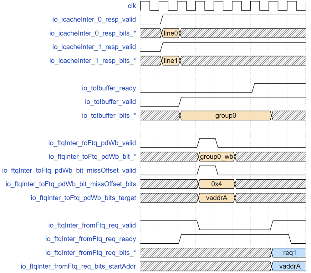
The above diagram shows the timing from when the instruction cache returns data to the IFU detecting a misprediction until the FTQ sends the correct address. The request corresponding to group0 fetches two cache lines, line0 and line1, in the f2 stage. In the next cycle, the IFU performs misprediction checks while simultaneously sending instructions to the Ibuffer. However, backend pipeline stalls cause the Ibuffer to fill up, lowering the ready signal at the Ibuffer's receiving end, keeping group0-related signals until the request is accepted by the Ibuffer. However, the writeback from IFU to FTQ is asserted in the cycle following tio_toIbuffer_valid, as the request has already entered the wb stage without blocking. This stage latches the PredChecker's results, reporting that the instruction at the 4th 2-byte position (0-indexed) in group0 was mispredicted and should redirect to vaddrA. After 4 cycles (flushing and re-running the predictor pipeline), the FTQ resends a prediction block starting at vaddrA to the IFU.
MMIO request interface timing example
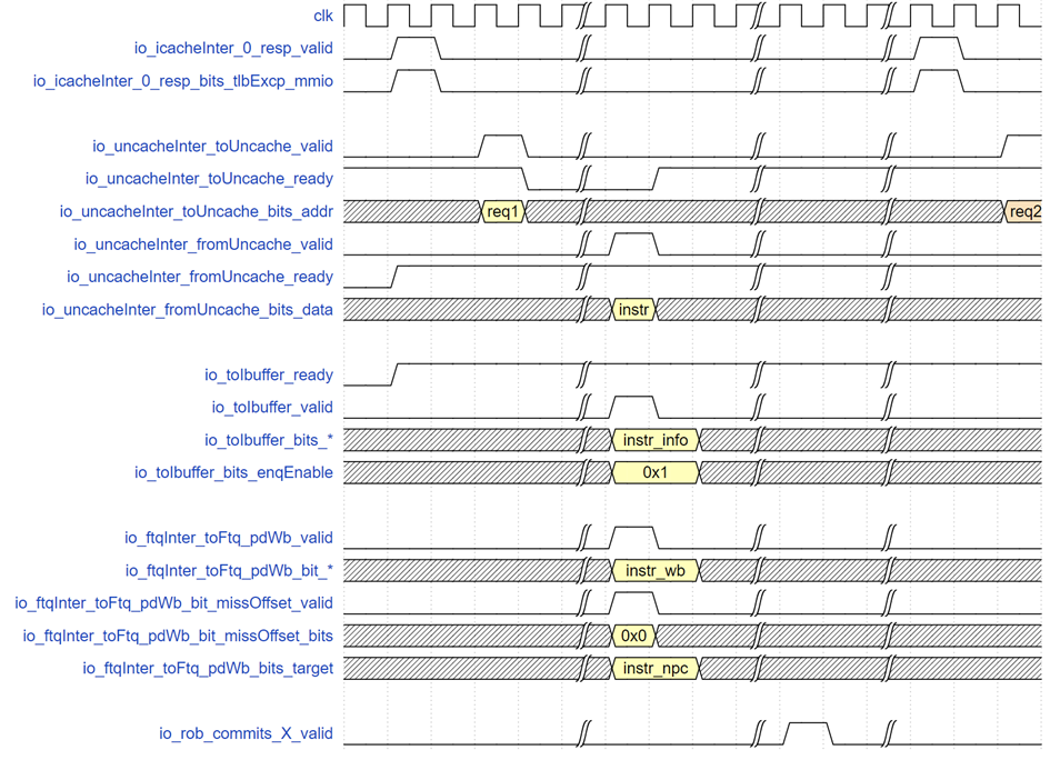
The above diagram illustrates the instruction fetch timing for an MMIO request, req1. Initially, the tlbExcp information returned by the ICache indicates that this is an instruction in MMIO space (other exception signals must remain low). After two cycles, the IFU sends a request to the InstrUncache. After some time, it receives the response along with the 32-bit instruction code. In the same cycle, the IFU sends this instruction as a predicted block to the IBuffer and writes back to the FTQ, reusing the misprediction signal port with the redirect address set to the next instruction's address. At this point, the IFU enters a wait state for instruction completion. Later, the rob_commits port reports the completion of this instruction's execution with no backend redirection. The IFU then reinitiates the instruction fetch request for the next MMIO instruction.
-
It is worth noting that the Svpbmt extension introduces an
NCattribute, representing a non-cacheable but idempotent memory region. This means we can speculatively execute inNCregions, i.e., we can send instruction fetch requests to the bus without "waiting for prior instructions to commit," manifesting as the state machine skipping the wait state. Implementation details can be found in #3944. ↩ -
In previous versions (riscv-debug-spec-draft, corresponding to XiangShan's PR#3693 merged on 2024.10.05), Chain also required the two Triggers'
mcontrol.timingto be identical. In the new version (riscv-debug-spec-v1.0.0),mcontrol.timinghas been removed. Currently, XiangShan's Scala implementation retains this bit, but its value is always 0 and cannot be written, and the generated Verilog code does not include it. Reference: https://github.com/riscv/riscv-debug-spec/pull/807. ↩