Kunming Lake BPU Module Documentation
Glossary of Terms
Table 1.1 Terminology
| abbreviation | Full name | ** describing ** |
|---|---|---|
| BPU | Branch Prediction Unit | Branch Prediction Unit |
| IFU | Instruction Fetch Unit | Fetch Unit |
| FTQ | Fetch Target Queue. | Fetch target queue |
| uFTB | Micro Fetch Target Buffer | Micro-op fetch target buffer |
| FTB | Fetch Target Buffer | Fetch Target Buffer. |
| TAGE | TAgged GEometric length predictor | A conditional branch predictor |
| SC. | Statistical Corrector Predictor | A conditional branch predictor used to correct TAGE predictions under statistically biased conditions |
| ITTAGE | Indirect Target TAgged GEometric length predictor | A branch predictor used to predict the target address of indirect jump instructions |
| RAS | Return Address Stack | A branch predictor used to predict the return address of a CALL instruction |
Design specifications
- Supports generating one branch prediction block and its corresponding predictor auxiliary information at a time.
- Supports bubble-free simple prediction
- Supports multiple precise predictors and coverage mechanisms
- Supports training predictors.
- Supports branch history maintenance and misprediction recovery
- Supports top-down performance event statistics
Functional Description
Functional Overview
The BPU module receives redirect signals from external backend execution units and subsequent pipeline stages. It uses multiple predictors to generate prediction blocks starting from the current PC value, along with internal meta information from each predictor, which is passed to the Fetch Target Queue (FTQ) for storage. The prediction blocks are used by the Instruction Fetch Unit (IFU), while the meta information is used for future predictor training and recovery. The BPU module employs a fully associative uFTB as a next-line predictor, generating a simple, bubble-free prediction result with an ideal latency of just one cycle. This result is directly passed to the FTQ as output. Simultaneously, this baseline prediction result flows through subsequent BPU pipeline stages for use by advanced prediction components to provide more accurate results. If an advanced predictor in a later stage produces a result inconsistent with the existing one, the advanced predictor's result will be used to update the prediction block stored in the FTQ and redirect the s0-stage PC, flushing incorrect results from earlier pipeline stages. Different types of instructions require different prediction information: conditional branch targets are provided by uFTB, requiring direction prediction; unconditional direct jump targets are provided by uFTB, requiring no special prediction; indirect jump directions do not need prediction, but the jump address provided by uFTB may be incorrect and requires prediction.
The advanced predictors in BPU include FTB, TAGE-SC, ITTAGE, and RAS. Among them, FTB is responsible for maintaining the start address, end address, branch instruction PC addresses, types (whether branch, jalr, jal, call, or return), and basic direction results of prediction blocks. TAGE-SC is the main predictor for conditional branch instructions, ITTAGE is used to predict indirect jump instructions, and RAS is responsible for predicting the jump address of return-type indirect jump instructions.
Multiple predictors within the prediction unit use branch prediction history as a condition for prediction. To improve the alignment between the history and the actual execution path, the branch prediction history is also speculatively updated along with the prediction results. The global branch history is maintained at the top level of the BPU using multiple update sources, adhering to the lengths required by TAGE, SC, and ITTAGE predictions. The maintenance algorithm is consistent across different branch history lengths. Specifically, TAGE uses branch history lengths of 8, 13, 32, and 119; ITTAGE uses lengths of 4, 8, 13, 16, and 32; and SC uses lengths of 0, 4, 10, and 16. The branch prediction history is uniformly maintained at the top level of the BPU module, with update sources prioritized from lowest to highest as follows: stalled branch history from s0, branch history updated using s1 prediction results, branch history updated using s2 prediction results, branch history updated using s3 prediction results, and branch history redirected from outside the BPU. The specific maintenance strategy for each branch history is as follows:
s0 stalled branch history: Does not perform any active updates and always remains consistent with the latest global folded history.
Branch history updated by s1 prediction results: Uses the branch prediction results from stage s1, passed along the pipeline.
s0 global folded history update. Specifically, the prediction result is shifted into the global branch history based on the branch prediction slot it occupies. If in slot 0, it is directly shifted in; if in slot 1, a 0 (slot 0 not taken) and the current prediction result are shifted in.
Branch history updated by s2 prediction results: Uses the branch prediction results from stage s2 as they propagate through the pipeline.
The global folded history is updated in s1. The update algorithm is the same as in s1. The s2 update only takes effect if the s2 prediction result differs from the previous s1 result.
The s3 update strategy is the same as s1 and s2, with updates only taking effect if the s3 result differs from previous s1 or s2 results.
Branch history updates for redirects occur only when a redirect happens. Depending on the addIntoHist signal in the redirect information, the returned branch history is either used directly or combined with the direction result of the redirected branch instruction to update BPU's global branch history.
To ensure relatively accurate prediction results, each branch predictor must continuously train itself using the latest execution results. Specifically, the predicted blocks to be updated and the meta information of each predictor's internal state at the time of prediction are generated in the FTQ module and fed back to the BPU unit for updating the predictors' internal states.
Branch prediction does not guarantee correctness. When the prediction result does not match the actual state, the state must be restored to before the erroneous prediction was used to update it, primarily involving the recovery of branch history and the redirection of the prediction block's starting address.
Branch prediction block and meta information generation.
Concept of branch prediction block
The purpose of branch prediction is to predict the direction and target of branch instructions in the execution flow, generating speculative PC range information for subsequent instruction fetches before the actual execution of the current instruction, ensuring continuous instruction supply.
A branch prediction block includes the valid bit (BranchPredictionBundle.valid), start address, complete prediction result, FTB entry, folded branch history, RAS predictor stack top, etc. The complete prediction result in the first pipeline stage comes from uFTB, while subsequent stages come from advanced predictors like FTB. The FTB entry is derived from uFTB and FTB read results.
The complete prediction result records the branch instruction's jump direction, whether the branch instruction information recorded in the block is valid (slot_valids, i.e., whether the branch instruction exists; one valid corresponds to one slot, one slot corresponds to one branch instruction in the prediction block, totaling 2 slots, where the last slot may record the second branch instruction in the block or an unconditional/indirect jump instruction), the branch instruction target, the jalr instruction target, the branch instruction's offset within the block, the end address of the instruction block when no jump occurs, whether the end address is incorrect (the block start address is greater than the end address, indicating a false hit), the type of the last branch instruction, whether the last instruction is an RVI call instruction, whether the second branch instruction slot records a branch instruction rather than an unconditional/indirect jump instruction, and whether it hit, among other information. As mentioned earlier, a prediction block can contain at most 2 branch instructions or 1 branch instruction + 1 unconditional jump instruction. When the actual number of instructions in the prediction block exceeds this limit, the subsequent FTQ module will split it. Additionally, if the prediction block contains no branch instructions or does not exceed the branch instruction limit but reaches the maximum width of the prediction block (32B), it will also be truncated.
The FTB entry records whether the entry is valid (FTB uses direct mapping; if the read address has never been written, the tag is invalid), the first branch instruction slot, the shared slot for the ending branch/jump, the end address, instruction type, whether the last instruction is an RVI call instruction, whether it always jumps, and other information. The FTB entry can be used to generate a complete prediction result.
Branch prediction block generation
The basic PC information in the branch prediction block is initially specified by the reset address passed from outside the module. During normal processor operation, it is continuously updated based on the predicted jump address of the prediction block. In case of misprediction, the PC value is updated according to the value provided by the redirect channel. The full prediction result for the next line is read from the uFTB module. In the full prediction result, the FTB entry is generated by the FTQ module based on past training results. The jump direction of conditional branch instructions is generated by uFTB and later updated by the TAGE-SC predictor. The jump address of indirect jump instructions is generated by uFTB and later updated by the ITTAGE predictor. The RAS predictor overrides the ITTAGE prediction result for return-type indirect jump instructions. The overridden result is only reflected in the predictor output and does not immediately feed back to update the internal state of the overridden predictor.
Meta information generation
To facilitate their own updates, each predictor will include internal state information (such as the index of the prediction table hit or the hit index at the time of prediction) as meta data, which is propagated along with the prediction results through the pipeline.
Bubble-Free Simple Prediction
The uFTB serves as the BPU's next-line predictor, providing the processor with bubble-free basic predictions to continuously generate the next speculative PC value.
uFTB Request Reception
During each valid phase 1 request, the tag is generated by extracting bits 16 to 1 of the incoming predicted block's starting PC and sent to the fully associative uFTB within this module for reading FTB entries. The FTB entry contents are as previously described. The uFTB contains 32 entries implemented with a fully associative register-based structure. Since registers are used, each entry can generate signals indicating whether it is a hit based on the validity of stored data and whether the stored tag matches the incoming information, along with the read FTB entry data, which is returned to the uFTB level within the same cycle.
uFTB Data Read and Return
In the current cycle, the uFTB memory has returned the hit signal and read data. In this stage, at most one hit entry will be selected from the returned hit signals to generate the prediction result. The algorithm for generating the complete prediction result is detailed in the subsequent FTB module. Here, the uFTB has an additional counter mechanism, adding a 2-bit-wide counter for up to two branch instructions within each uFTB entry. If the counter is greater than 1 or the always_taken flag in the FTB entry is valid (the latter mechanism also exists in the FTB module), the prediction result is a jump. Additionally, the hit signal and selected hit way number from this stage are also used as meta information for this predictor, waiting to be sent out with other predictors in stage s3 and stored in FTQ along with the final prediction result. This predictor has no additional actions in stages 2 and 3.
uFTB Data Update
When all instructions corresponding to the prediction block are committed, the update channel from FTQ to BPU, which connects directly to this module, will include the FTB entry updated by the FTQ module based on instruction commit information. Since the fully associative uFTB is entirely built with registers, write operations do not affect parallel read operations, and the incoming update information is always used for updates. When the update channel is valid, the update PC value is used in the same cycle to generate a tag and match it with existing entries in the uFTB, producing match and match way signals. In the next cycle, if a match exists, the write signal for the matched way is asserted; otherwise, a pseudo-LRU replacement algorithm selects a way to replace, and the corresponding write signal is asserted. The write data is the updated FTB entry.
Maintenance of the counters for each branch instruction is also updated when the update channel is asserted. In the cycle following the update channel assertion, the counters for the branching instructions within the updated FTB entry and those before it are updated. If the branch is taken, the counter is incremented by 1; if not taken, it is decremented by 1. If the counter is saturated (0 or all 1s), the current value is maintained.
The pseudo-LRU algorithm also requires data updates, with two data sources: one is the way encoding of the hit during prediction, and the other is the way encoding to be written during uFTB updates. If either is valid, its information is used to update the pseudo-LRU state. If both are valid in the same cycle, combinational logic is used to update the state sequentially with both pieces of information.
Multiple advanced predictors and coverage mechanisms
The outputs from each advanced predictor will be compared with the results previously generated by pipeline stages and propagated through the pipeline (either the minimal results from uFTB or the completed results provided by FTB in later stages). If discrepancies are found, the pipeline will be flushed with the newer results.
Composer
Composer is a module used to combine multiple predictors. In this project, it combines five predictors—uFTB, FTB, TAGE-SC, ITTAGE, and RAS—and abstracts them into a three-stage pipelined coverage predictor. Each predictor in Composer can be toggled via custom register writes to sbpctl, allowing selective use of predictors. Upon detecting an external redirect, Composer sends the redirect request to each predictor for recovering speculatively updated elements. After all instructions in the prediction block are committed, the predictors in Composer undergo training. Finally, Composer outputs the three-stage prediction results to Predictor. The meta information of each predictor is concatenated in this module and passed to FTQ, and the training meta information returned by FTQ is also split in this module and sent to each predictor.
Configuration of the starting PC
Composer's IO interface io_reset_vector enables configuration of the starting PC. The desired starting PC only needs to be passed to this IO.
Connection with Predictors
The Composer connects the five predictors: uFTB, FTB, TAGE-SC, ITTAGE, and RAS. There are three pipeline stages for branch predictors, with the same stages of each predictor connected sequentially from front to back via combinational logic. Since each predictor has a fixed latency and completes its prediction by a specific stage, the Composer only needs to output the corresponding predictor's results at the respective pipeline stage.
Predictor enable/disable
Through Zicsr instructions, we can read and write the custom CSR sbpctl to control the enablement of various predictors in Composer. sbpctl[6:0] represents the enablement of seven predictors: {LOOP, RAS, SC, TAGE, BIM, BTB, uFTB}. A high level indicates enablement, while a low level indicates disablement. Specifically, the value of the spbctl CSR is transmitted to each predictor via Composer's IO interface io_ctrl_*, with each predictor responsible for implementing its enablement. The current architecture does not include the Loop and BIM predictors, so their corresponding bits are invalid.
Redirection recovery
The Composer receives redirection requests through IO ports such as io_s2_redirect, io_s3_redirect, and io_redirect_*. These requests are sent to its predictors to recover speculatively updated elements, such as the top item of the RAS stack.
FTB
The FTB temporarily stores FTB entries, providing advanced predictors like TAGE, ITTAGE, SC, and RAS with more accurate branch instruction locations, types, target addresses, and other key branch prediction block information. It also offers basic direction prediction for always-taken branch instructions. The FTB module contains an FTBBank module responsible for the actual storage of FTB entries, utilizing a multi-port SRAM as the storage medium. The SRAM specifications and format are detailed later.
Request reception
In stage 0, the FTB module sends a read request to the internal FTBBank, with the request PC value being the PC passed from s0.
Data read and return
In the next clock cycle after sending the request, which is stage 1 of the predictor, the multi-path signals read from the FTB SRAM will be temporarily stored.
In the next cycle, i.e., stage 2 of the predictor, the hit signal is generated based on the tag matching between the stored data and the tag derived from the high bits of the PC during the actual request. If a hit occurs, the selected FTB entry and the hit way information are returned. If no hit occurs, the output data is meaningless.
The data read from the FTBBank module is passed as a stage 2 prediction result within the FTB module to the s2 stage of subsequent BPU predictors to obtain branch instruction type and PC information. Additionally, this read result is temporarily stored in the FTB module and passed as a prediction result in stage 3 via combinational logic to subsequent predictors. If the FTB hits, the hit way number, hit information, cycle count, etc., are also propagated downstream with the pipeline. Ultimately, if the prediction block is not flushed midway through the pipeline, it is passed as meta information to the subsequent FTQ module in s3. The cycle count is only used for performance statistics in simulation environments and does not exist in FPGA environments.
Additionally, if a valid branch instruction recorded in the FTB entry has an "always taken" flag, indicating that the branch instruction has never had a non-jump case historically, the corresponding br_taken_mask in the phase 2 prediction result is directly set high within this module. This directly predicts the branch instruction as taken, bypassing the prediction results from other advanced predictors.
TAGE-SC
TAGE-SC is the main predictor for conditional branches in the Nanhu architecture, classified as an Accurate Predictor (APD).
Among them, TAGE utilizes multiple prediction tables with different history lengths to mine extremely long branch history information; SC is a statistical corrector.
TAGE consists of a base prediction table and multiple history tables. The base prediction table is indexed by the PC, while the history tables are indexed by the XOR result of the PC and a folded version of the branch history of a certain length. Different history tables use branch histories of varying lengths. During prediction, a tag is also calculated by XORing the PC with another folded version of the branch history corresponding to each history table, which is then matched against the tag read from the table. A match indicates a hit for that table. The final result depends on the prediction from the history table with the longest matching history length.
When SC determines that TAGE has a high probability of misprediction, it inverts the final prediction result.
In the Nanhu architecture, each prediction can simultaneously predict up to two conditional branch instructions. When accessing various history tables of TAGE, the starting address of the prediction block is used as the PC, and two prediction results are fetched simultaneously, both using the same branch history.
TAGE Prediction Timing
TAGE is a high-accuracy conditional branch direction predictor. It uses branch histories of different lengths and the current PC value to index multiple SRAM tables. When a hit occurs in multiple tables, the prediction result from the entry with the longest matching history is selected as the final result.
TAGE requires a 2-cycle delay:
- Generates the SRAM addressing index in 0 cycles. The index generation process involves XORing the folded history with the PC. The management of the folded history is not handled within ITTAGE and TAGE but within the BPU.
- 1-cycle Readout Result
- 2-cycle output prediction result
TAGE: Folded History
Each history table in TAGE-type predictors has a specific history length. To index the history table after XORing with the PC, long branch history sequences are divided into multiple segments, all of which are XORed together. The length of each segment is generally equal to the logarithm of the history table depth. Due to the typically high number of XOR operations, to avoid the latency of multi-level XORs on the prediction path, we directly store the folded history. Since different history lengths require different folding methods, the number of folded history copies needed equals the count of unique (history length, folded length) tuples. When updating a single bit of history, only the oldest and newest bits before folding need to be XORed into the corresponding positions, followed by a shift operation.
TAGE: Alternative prediction logic
The USE_ALT_ON_NA register is implemented to dynamically decide whether to use an alternate prediction when the confidence in the longest history match result is insufficient. For timing considerations, the base prediction table result is always used as the alternate prediction, which results in minimal accuracy loss.
SC: Timing
In some applications, certain branch behaviors exhibit a statistical prediction bias with weak correlation to branch history or path. For these branches, using counters to capture statistical bias is more effective than TAGE. TAGE is highly effective in predicting strongly correlated branches but fails to predict branches with statistical bias, such as those with a slight deviation in one direction but no strong correlation to historical paths.
The purpose of statistical correction is to detect less reliable predictions and recover them. Predictions from TAGE, along with branch information (address, global history, global path, local history), are presented to the statistical correction predictor, which decides whether to invert the prediction. SC is responsible for predicting conditionally biased branch instructions and reversing the TAGE predictor's outcome in such cases.
SC's prediction algorithm relies on signals from TAGE, such as whether there is a history table hit (provided) and the provider's prediction result (taken), to determine its own prediction. The provided signal is one of the necessary conditions for using SC prediction, while the provider's taken serves as the choose bit to select SC's final prediction. This is because SC may yield different predictions depending on TAGE's varying outcomes.
SC requires a 3-cycle delay:
- 0-cycle generation of the addressing index s0_idx. The index is generated by XORing the folded history with the PC. The management of the folded history is not within ITTAGE or TAGE but within the BPU.
-
- Read out the counter data s1_scResps corresponding to s0_idx from the SCTable.
- In the second cycle, determine whether the prediction result needs to be inverted based on s1_scResps.
- Three cycles to output the complete prediction result.
ITTAGE
ITTAGE receives prediction requests from within the BPU. It consists of a base prediction table and multiple history tables, each entry containing a field to store the target address of indirect jump instructions. The base prediction table is indexed by PC, while history tables are indexed by XORing the PC with a folded result of a certain length of branch history. Different history tables use varying lengths of branch history. During prediction, a tag is computed by XORing the PC with another folded result of the branch history corresponding to each history table, then matched against the tag read from the table. A match indicates a hit. The final result depends on the outcome from the history table with the longest matching history length. Ultimately, ITTAGE outputs the prediction result to the composer.
Prediction of indirect jump instructions
ITTAGE is used to predict indirect jump instructions. The jump targets of ordinary branch instructions and unconditional jump instructions are directly encoded in the instructions, making them easy to predict. However, the jump addresses of indirect jump instructions come from runtime-variable registers, leading to multiple possible choices, requiring prediction based on branch history. To this end, each entry in ITTAGE adds a predicted jump address field on top of the TAGE entry, with the final output being the selected predicted jump address rather than the predicted jump direction. Since each FTB entry stores at most one indirect jump instruction, the ITTAGE predictor predicts the target address of at most one indirect jump instruction per cycle.
ITTAGE requires a 3-cycle delay:
- Index generation takes 0 cycles.
- 1 Read out data
- 2-cycle selection of hit results
- 3-cycle output
Folded Branch History
The history table has a specific history length. To index the history table after XORing with the PC, a long branch history sequence must be divided into multiple segments, all of which are then XORed together. Each segment's length typically equals the logarithm of the history table's depth. Due to the generally high number of XOR operations, storing the folded history directly avoids the delay of multi-level XOR operations in the prediction path. Since different history lengths require different folding methods, the number of folded history copies needed equals the count of unique (history length, folded length) tuples. When updating a single bit of history, only the oldest and newest bits need to be XORed into their respective positions, followed by a shift operation.
RAS
The RAS uses a stack structure to predict the return addresses of execution flows with paired matching characteristics, such as function calls and returns. The call (push/call) type instructions are characterized by jal/jalr instructions with target register addresses of 1 or 5. The return (ret) type instructions are characterized by jalr instructions with source registers of 1 or 5. These are unconditional jump instructions, and their type and offset within the block are already read from the FTB.
In the implementation, the RAS predictor provides prediction results in both the s2 and s3 stages.
Stage 2 results.
In stage 2, since the s3 stage may still have prediction results requiring updates, the current FTB entry is not necessarily the final execution path. The prediction made at this stage assumes that the s3 prediction result (i.e., the previous prediction block) will not refresh the predicted start address in the current pipeline stage. If the FTB entry passed from FTB in stage 2 is valid and contains a push-type (call) instruction, the PC value of the next instruction after this instruction is pushed onto the RAS stack. If the FTB entry passed in s2 is valid and contains a pop-type (return) instruction, the address at the top of the stack is returned as the result, and the result is popped from the stack.
Within the RAS stack module, the above behaviors are reflected as follows: During a push operation, if the current address differs from the top-of-stack address, a new entry with a counter value of 0 is pushed onto the stack; otherwise, the counter of the top entry is incremented by 1. Both operations require setting this top information as a write bypass entry for current read operations. During a pop operation, if the counter of the top entry is 0, the top pointer is decremented by 1; if the counter is greater than 0, the counter is decremented by 1. For timing optimization, data written to the RAS stack is delayed by one cycle. Considering cases where data written in the current cycle may need to be read in the next cycle, a write bypass mechanism is designed. Data to be written is first used in the current cycle to update write bypass-related entries, including the write pointer and write data. If the read pointer requested in the next cycle matches the write bypass pointer, the bypass value is used; otherwise, the actual top-of-stack value is used.
Stage 3 result
In stage 3, the speculative push/pop operation records that occurred in stage 2 are passed along the pipeline. Stage 3 generates push/pop control signals using the same logic as stage 2, based on the FTB entry in stage 3 (at this point, there are no subsequent pipeline stages, meaning FTB entries that reach stage 3 will not be flushed by later stages). If it is found that the speculative result from stage 2 differs from the determined result in stage 3—i.e., when the RAS was in stage 2, stage 3 had predicted a flush of the BPU pipeline—then the prediction result from stage 2 was based on a scenario that has since changed, and the RAS stack operation was incorrect. State recovery similar to misprediction is required, with specific details to follow.
Predictor training
Every prediction made by the predictor, after all instructions in it are successfully committed, generates prediction block update information by the FTQ. This information, along with the meta information from each predictor passed to the FTQ, is sent back to the predictor for training.
Predictor Training Data Reception
The predictor training data passed from FTQ to the BPU module, along with FTB entries, updated PC, and other signals, is forwarded to each predictor. Each predictor either temporarily stores the update signal or processes it immediately, depending on its timing pressure.
FTB
For the specific update logic of FTB entries, please refer to the FTQ module.
Upon receiving an update request, the FTB module determines the update timing based on whether the original read result was a hit, as recorded in the meta information. If the meta indicates a hit during prediction, the new FTB data is immediately written to SRAM in the current cycle. Otherwise, the update is delayed by 2 cycles to wait for the existing FTB result to be read out and determine the write path before updating.
Within the FTBBank, when an update request exists, the module's behavior differs depending on whether it is an immediate or delayed update. For immediate updates, the SRAM write channel in the FTBBank is activated, and the write is completed based on the given information. For a 2-cycle delayed update, the FTBBank first receives a read request for the update, which takes priority over regular prediction read requests. In the next cycle, the data is read out, and the path encoding that matches the given address is passed to the external FTB module (hit scenario: two requests for this FTB entry, the first request missed, and before its update, a second access occurred. The update corresponding to the first request is now complete, and this update is for the second request). If there is no hit in this cycle, the write is performed in the next cycle to a path selected by the path allocation algorithm after reading the FTB entry. The path selection rule is as follows: if all paths are full, the replacement algorithm (here, pseudo-LRU; see the ICache documentation for details) selects the path to replace; otherwise, an empty path is chosen.
Composer
The Composer sends training signals to its predictors through the IO port io_update_*. In general, to prevent contamination of predictor contents by incorrect execution paths, each predictor is trained after all instructions in the prediction block are committed. Their training content comes from their own prediction information and the decoding and execution results of instructions in the prediction block, which are read from the FTQ and sent back to the BPU. The prediction information is packed and stored in the FTQ after prediction; the decoding results of instructions come from the IFU's pre-decoding module and are written back to the FTQ after fetching the instructions; and the execution results come from various execution units.
TAGE-SC & ITTAGE
Each entry contains a useful field. A non-zero value indicates that the entry is useful and will not be allocated as an empty entry during training. During training, a saturating counter dynamically monitors the success/failure rate of allocations. When the number of allocation failures is sufficiently high and the counter saturates, all useful fields are cleared.
RAS
When the speculative result of RAS in stage 2 differs from stage 3 or a previous prediction result encounters a redirect, the state must be recovered. The redirect information is temporarily stored in RAS registers before actual recovery, delayed by one cycle before updating. Stage 3 detects the difference and completes the update in the next cycle. If it is a call misprediction in the redirect (the erroneous instruction is pre-decoded as a call-type instruction) or a stage 3 push operation mismatch, a recover_push operation is performed to push the erroneously popped RAS stack top back in. If it is a ret misprediction in the redirect (the erroneous instruction is pre-decoded as a pop instruction) or a stage 3 pop operation mismatch, a recover_pop operation is performed to pop the address that should have been popped from the RAS stack top. The stack pointer is restored to the one transmitted by the redirect during redirection; otherwise, it remains the current value. The stack top is restored to the stack top item transmitted by the redirect during recovery; otherwise, it remains the current value. The new recovery address is the value of the next instruction under the redirect signal during redirection; otherwise, it is the speculative value from stage 2.
Within the RAS stack, state recovery also generates operations such as push and pop. The handling of these operations is the same as in the aforementioned two stages, with only differing cases listed here. For a push operation without allocating a new entry, if in the recover state, the sp, stack top pointer, and top return address are set to updated values. For a pop operation when the current stack top counter is not 0, the so, stack top pointer, and top return address are set to updated values. For operations that are neither push nor pop, the sp, stack top pointer, and top return address must be restored while handling write bypass.
Branch history information maintenance
Speculative Update
After the predictor generates speculative results in the pipeline stage, subsequent requests will include this speculative value in the branch history to improve prediction accuracy.
redirect recovery
When encountering a branch prediction error, the branch history is also restored to its state before the error, ensuring the accuracy of the branch history.
Top-down performance analysis event statistics.
In the BPU pipeline stages, predictor-generated speculative results may stall for various reasons, potentially leading to pipeline bubbles in the processor. To accurately analyze and locate performance bottlenecks, the Kunming Lake architecture includes top-down performance counters that collect stall/blockage information from each pipeline stage and attribute pipeline bubbles (the difference between the actual number of committed instructions and the ideal issue count) to specific modules, enabling precise bottleneck identification. The details of this performance analysis and modeling method are described in Intel's paper, "A Top-Down Method for Performance Analysis and Counters Architecture." Stalling events that can be tracked within the BPU include pipeline bubbles caused by misprediction recovery from various predictors, recovery from backend memory access violations, pipeline bubbles due to BPU-internal override predictions flushing older results, bubbles caused by BPU stalls during branch instruction training, and bubbles due to FTQ being full and unable to accept new branch prediction blocks. The BPU does not prioritize the causes of bubbles but simply raises the bubble control signal when the corresponding statistical conditions are met and propagates it through the processor pipeline.
Currently, the BPU contains five predictors: FTB (including uFTB and main FTB), TAGE, SC, ITTAGE, and RAS. Topdown further breaks down branch misprediction causes into these five predictors. Specifically, the conditions for attributing each misprediction bubble to the respective predictors are:
- FTB: A branch instruction-related redirection occurred, and the mispredicted instruction was not recorded in the corresponding prediction block's FTB.
- TAGE: A branch instruction-related redirect occurred, and the mispredicted instruction is recorded in the corresponding prediction block's FTB, but the SC predictor did not provide the corresponding prediction.
- SC: A branch instruction-related redirect occurs, and the mispredicted instruction is recorded in the FTB of the corresponding prediction block, while the SC predictor provides the corresponding prediction result.
- ITTAGE: A branch instruction-related redirect occurred, with the mispredicted instruction being a jalr instruction but not a return instruction, and it hit in the FTB entry.
- RAS: A branch instruction-related redirect occurred. The mispredicted instruction is a return instruction (a special type of jalr instruction; see the subsequent RAS module description for details).
The condition for pipeline bubbles introduced by backend memory violation recovery is that the redirect signal from the backend indicates the redirect is due to a memory violation.
Pipeline bubbles caused by internal BPU overrides have two possible sources: the redirect signals from the second and third pipeline stages of the BPU.
Pipeline bubbles introduced by branch predictor training have three possible sources: the ready signals of BPU's first, second, and third pipelines. These ready signals are the result of an OR operation on the ready signals from each predictor within the BPU.
The condition for pipeline bubble insertion due to FTQ being full is determined by the ready signal of the handshake interface from the BPU to the FTQ module being pulled low.
Bubbles caused by branch mispredictions and memory violations will be marked in the topdown signals of each BPU pipeline stage. Bubbles introduced by BPU internal overrides will be marked in the current pipeline stage of the override and earlier stages, without affecting the pipeline stages of prediction blocks earlier than this override. The handling of bubbles caused by branch predictor training is similar to BPU overrides.
Overall design
Overall Block Diagram

Interface timing
BPU to FTQ Interface Timing

The above diagram shows the timing of the prediction result interface from BPU to FTQ. For the prediction results starting at address 0x1FFFF80020, outputs are generated in pipeline stages 1, 2, and 3, respectively. If the result differs from the previous pipeline stage, the redirect signal is raised to indicate the need to flush the prediction pipeline.
FTQ to BPU redirect interface timing.
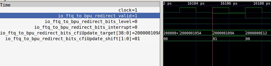
The above diagram shows the timing of the redirect interface from FTQ to BPU.
The core signal of redirect is cfiUpdate_target, which specifies the redirect
target address as 0x200000109a.
FTQ to BPU update interface timing

The diagram above illustrates the timing of the update interface from FTQ to BPU. This update prepares for the prediction block starting at 0x2000000e00, with a target jump address of 0x200000e0e.
Register Configuration
| register | address | reset value | attribute | ** describing ** |
|---|---|---|---|---|
| sbpctl | 0x5C0 | 64'd0 | RW | bit0: uFTB enable signal bit1: FTB enable signal bit2: BIM enable signal (reserved) bit3: TAGE enable signal bit4: SC enable signal bit5: RAS enable signal bit6: loop predictor enable signal (reserved) |
Note: RO—Read-only register; RW—Read-write register.
Reference documents
- Reinman G, Austin T, Calder B. A scalable front-end architecture for fast instruction delivery[J]. ACM SIGARCH Computer Architecture News, 1999, 27(2): 234-245.
- Perais A, Sheikh R, Yen L, et al. Elastic instruction fetching[C]//2019 IEEE International Symposium on High Performance Computer Architecture (HPCA). IEEE, 2019: 478-490.
- Software Optimization Guide for AMD Family 19h Processors (PUB), Chap. 2.8.1.5, https://www.amd.com/system/files/TechDocs/56665.zip
- Seznec A, Michaud P. A case for (partially) TAgged GEometric history length branch prediction[J]. The Journal of Instruction-Level Parallelism, 2006, 8: 23.
- Seznec A. A 256 kbits l-tage branch predictor[J]. Journal of Instruction-Level Parallelism (JILP) Special Issue: The Second Championship Branch Prediction Competition (CBP-2), 2007, 9: 1-6.
- Seznec A. A new case for the tage branch predictor[C]//Proceedings of the 44th Annual IEEE/ACM International Symposium on Microarchitecture. 2011: 117-127.
- Seznec A. The O-GEHL branch predictor[J]. The 1st JILP Championship Branch Prediction Competition (CBP-1), 2004.
- Jiménez D A, Lin C. Dynamic branch prediction with perceptrons[C]//Proceedings HPCA Seventh International Symposium on High-Performance Computer Architecture. IEEE, 2001: 197-206.
- Seznec A. A 64-Kbytes ITTAGE indirect branch predictor[C]//JWAC-2: Championship Branch Prediction. 2011.