Secondary Module L1 TLB
Design specifications
- Supports receiving address translation requests from the Frontend and MemBlock.
- Supports the PLRU replacement algorithm.
- Supports returning physical addresses to the Frontend and MemBlock.
- Both ITLB and DTLB use non-blocking access. Specifically, for MMIO address translation requests, ITLB uses blocking access.
- Both ITLB and DTLB entries are implemented using register files
- Both ITLB and DTLB entries are fully associative structures
- ITLB and DTLB adopt the current privilege level of the processor and the effective privilege level for memory access execution
- Support for determining whether virtualization is enabled and whether two-stage translation is enabled within the L1 TLB
- Support sending PTW requests to L2 TLB
- The DTLB supports copying the returned physical address.
- Support for exception handling
- Support for TLB compression
- Support TLB Hint mechanism
- Stores four types of TLB entries
- TLB refill merges page tables of two stages
- Hit detection logic for TLB entries
- Support for re-sending PTW to obtain gpaddr after a guest page fault
Function
Receives address translation requests from the Frontend and MemBlock.
Memory reads and writes within the core, including frontend instruction fetch and backend memory access before the access, require address translation by the L1 TLB. Due to the large physical distance and to avoid mutual interference, they are divided into the ITLB (Instruction TLB) for frontend instruction fetch and the DTLB (Data TLB) for backend memory access. The ITLB uses a fully associative mode, with 48 entries fully associative storing all page sizes. The ITLB receives address translation requests from the Frontend; itlb_requestors(0) to itlb_requestors(1) come from IPrefetch in the icache; itlb_requestors(2) comes from ifu, for address translation requests of MMIO instructions. Specifically, blocking ITLB is used for MMIO address translation.
The configuration of ITLB entries and request sources are detailed in 此表、此表.
| Item name | item count | **Organization structure ** | Replacement Algorithm | stored content |
|---|---|---|---|---|
| Page | 48 | Fully associative | PLRU | All size pages |
| Serial number | Source |
|---|---|
| requestors(0) | Icache |
| requestors(1) | Icache |
| requestors(2) | IFU |
Xiangshan's memory access channel has 3 Load pipelines, 2 Store pipelines, as well as an SMS prefetcher and an L1 Load stream & stride prefetcher. To handle numerous requests, the three Load pipelines and the L1 Load stream & stride prefetcher use the Load DTLB, the two Store pipelines use the Store DTLB, and prefetch requests use the Prefetch DTLB, totaling 3 DTLBs, all employing the PLRU replacement algorithm (see Section 5.1.1.2).
DTLB uses a fully associative mode, with 48 entries fully associative storing all page sizes. DTLB receives address translation requests from MemBlock; dtlb_ld receives requests from loadUnits, VSegmentUnit, and the L1 Load stream & stride prefetcher, responsible for address translation of Load instructions; dtlb_st receives requests from StoreUnits, responsible for address translation of Store instructions. Specifically, for AMO instructions, loadUnit(0)'s dtlb_ld_requestor is used to send requests to dtlb_ld. The SMSPrefetcher and prefetches from L2 send prefetch requests to a separate DTLB.
The configuration and request sources of DTLB entries are as shown in 此表、此表.
| Item name | item count | **Organization structure ** | Replacement Algorithm | stored content |
|---|---|---|---|---|
| Page | 48 | Fully associative | PLRU | All size pages |
| ** module ** | Serial number | Source |
|---|---|---|
| DTLB_LD | ||
| ld_requestors(0) | loadUnit(0), AtomicsUnit, VSegmentUnit | |
| ld_requestors(1) | loadUnit(1) | |
| ld_requestors(2) | loadUnit(2) | |
| ld_requestors(3) | L1 Load stream & stride Prefetch. | |
| DTLB_ST | ||
| st_requestors(0) | StoreUnit(0) | |
| st_requestors(1) | StoreUnit(1) | |
| DTLB_PF | ||
| pf_requestors(0) | SMSPrefetch | |
| pf_requestors(1) | L2 Prefetch |
Uses the PLRU replacement algorithm
L1 TLB employs a configurable replacement policy, defaulting to the PLRU algorithm. In the Nanhu architecture, both ITLB and DTLB include NormalPage and SuperPage, complicating the refill strategy. ITLB's NormalPage handles 4KB page translations, while SuperPage handles 2MB and 1GB page translations, requiring entries to be filled into NormalPage or SuperPage based on the refilled page size (4KB, 2MB, or 1GB). DTLB's NormalPage handles 4KB page translations, while SuperPage handles all page sizes. NormalPage uses direct mapping with many entries but low utilization. SuperPage is fully associative with high utilization but fewer entries due to timing constraints, resulting in a high miss rate.
Note that the Kunminghu architecture optimizes the above issues by unifying the ITLB and DTLB as 48-entry fully associative structures under timing constraints, allowing any page size to be refilled. Both ITLB and DTLB use the PLRU replacement strategy.
The refill policies for ITLB and DTLB are shown in 此表.
| ** module ** | Item name | Policy |
|---|---|---|
| ITLB | ||
| Page | 48 entries fully associative, can refill pages of any size | |
| DTLB | ||
| Page | 48 entries fully associative, can refill pages of any size |
Returns the physical address to the Frontend and MemBlock.
After obtaining the physical address from the virtual address in the L1 TLB, the corresponding physical address of the request, along with information such as whether a miss occurred, guest page fault, page fault, or access fault, is returned to the Frontend and MemBlock. For each request in the Frontend or MemBlock, a response is sent by the ITLB or DTLB, indicated by tlb_requestor(i)_resp_valid to signify the response is valid.
In the Nanhu architecture, although SuperPage and NormalPage are physically implemented using register files, SuperPage is a 16-entry fully associative structure, while NormalPage is a direct-mapped structure. After reading data from the direct-mapped NormalPage, a tag comparison is required. Despite the SuperPage having 16 fully associative entries, only one entry can be hit at a time, which is marked by hitVec to select the data read from the SuperPage. The time taken to read data + tag comparison in NormalPage is significantly longer than reading data + selecting data in SuperPage. Therefore, from a timing perspective, the dtlb returns a fast_miss signal to the MemBlock, indicating a SuperPage miss, and a miss signal indicating both SuperPage and NormalPage misses.
Meanwhile, in the Nanhu architecture, due to tight timing constraints for PMP & PMA checks in the DTLB, the PMP is divided into dynamic and static checks (see Section 5.4). When the L2 TLB's page table entry is refilled into the DTLB, the refilled entry is simultaneously sent to the PMP and PMA for permission checks, with the results stored in the DTLB. The DTLB must additionally return a signal indicating the validity of the static check and the check results to the MemBlock.
It is important to note that the Kunminghu architecture optimizes TLB query configurations and corresponding timing. Currently, fast_miss has been removed, and no additional static PMP & PMA checks are required. However, these may be reinstated in the future due to timing or other reasons. For documentation completeness and compatibility, the previous two sections are retained. The Kunminghu architecture has eliminated fast_miss and static PMP & PMA checks—please take note again.
Blocking and non-blocking accesses
In the Nanhu architecture, the frontend's instruction fetch requires blocking access to the ITLB, while the backend's memory access requires non-blocking access to the DTLB. In reality, the TLB itself is non-blocking and does not store request information. The reason for blocking or non-blocking access lies in the requirements of the request source. When the frontend encounters a TLB miss during instruction fetch, it must wait for the TLB to retrieve the result before sending the instruction to the processor backend for processing, resulting in a blocking effect. In contrast, memory operations can be scheduled out-of-order. If one request misses, another load/store instruction can be scheduled for execution, thus exhibiting a non-blocking effect.
The above functionality in the Nanhu architecture is implemented via TLB, where control logic ensures that after an ITLB miss, it continuously waits for the PTW to retrieve the page table entry. In Kunminghu, this functionality is guaranteed by ICache, where after an ITLB miss is reported to ICache, ICache continuously resends the same request until a hit, ensuring non-blocking access.
However, it should be noted that the DTLB of the Kunminghu architecture is non-blocking, the first two channels of the ITLB are non-blocking, but for MMIO address translation requests, the ITLB is blocking.
Storage structure of L1 TLB entries.
Xiangshan's TLB allows configuration of organizational structures, including associative modes, entry counts, and replacement policies. The default configuration is: both ITLB and DTLB are 48-entry fully associative structures, implemented by register files (see Section 5.1.2.3). If simultaneous read and write operations to the same address occur in the same cycle, results can be obtained directly via bypass.
Reference ITLB or DTLB configuration: Both use a fully associative structure, with entry counts of 8 / 16 / 32 / 48. Currently, parameterized modification of the TLB structure (fully associative / set-associative / direct-mapped) is not supported; manual code modification is required.
Support for determining whether virtualization is enabled and whether two-stage translation is enabled within the L1 TLB
XiangShan supports the Sv39/Sv48 page tables in the RISC-V manual, with a virtual address length of 39/48 bits. XiangShan's physical address is 48 bits and is configurable.
Whether virtual memory is enabled is determined jointly by the privilege level and the MODE field of the SATP register. This decision is made inside the TLB and is transparent to components outside the TLB. For a description of privilege levels, see Section 5.1.2.7; regarding the MODE field of SATP, the Kunming Lake architecture of XiangShan supports MODE field values of 8/9, i.e., the Sv39/Sv48 paging mechanism; otherwise, an illegal instruction fault will be raised. To modules outside the TLB (such as Frontend, LoadUnit, StoreUnit, AtomicsUnit, VSegmentUnit, etc.), all addresses have undergone address translation by the TLB.
When the H extension is added, enabling address translation also requires determining whether two-stage address translation is active. Two-stage address translation is triggered under two conditions: first, when executing a virtualization memory access instruction, and second, when virtualization mode is enabled and the MODE field of VSATP or HGATP is non-zero. The translation modes in this scenario are as follows. The translation mode is used to search for the corresponding type of page table in the TLB and to send PTW requests to the L2TLB.
| VSATP Mode | HGATP Mode | Translation Mode |
|---|---|---|
| non-zero | non-zero | allStage, both translation stages present |
| non-zero | 0 | onlyStage1, only first-stage translation |
| 0 | non-zero | onlyStage2, indicating only second-stage translation. |
Privilege level of L1 TLB.
According to the RISC-V manual, the privilege level for the frontend instruction fetch (ITLB) is the current processor privilege level, while the privilege level for backend memory access (DTLB) is the effective privilege level for memory access. Both the current processor privilege level and the effective memory access privilege level are determined in the CSR module and passed to the ITLB and DTLB. The current processor privilege level is stored in the CSR module. The effective memory access privilege level is jointly determined by the MPRV, MPV, and MPP bits of the mstatus register, and the SPVP bit of the hstatus register. If a virtual memory access instruction is executed, the effective memory access privilege level is the privilege level stored in the SPVP bit of the hstatus register. If the executed instruction is not a virtual memory access instruction and the MPRV bit is 0, the effective memory access privilege level is the same as the current processor privilege level, and the effective virtualization mode for memory access is consistent with the current virtualization mode. If the MPRV bit is 1, the effective memory access privilege level is the privilege level stored in the MPP field of the mstatus register, and the effective virtualization mode for memory access is the virtualization mode stored in the MPV bit of the hstatus register. The privilege levels of the ITLB and DTLB are shown in the table.
| ** module ** | Privilege Level |
|---|---|
| ITLB | Current processor privilege level |
| DTLB | When executing a non-virtualized memory access instruction, if mstatus.MPRV=0, the privilege level and virtualization mode are those of the current processor; if mstatus.MPRV=1, the privilege level is stored in mstatus.MPP and the virtualization mode is stored in hstatus.MPV. |
Send PTW request
When an L1 TLB miss occurs, a Page Table Walk request must be sent to the L2 TLB. Due to the significant physical distance between L1 TLB and L2 TLB, intermediate pipeline stages, known as Repeaters, are required. Additionally, the repeater must filter out duplicate requests to prevent redundant entries in the L1 TLB (see Section 5.2). Hence, the first-level Repeater for ITLB or DTLB is also referred to as a Filter. The L1 TLB sends PTW requests and receives PTW responses via the Repeater to/from the L2 TLB (see Section 5.3).
DTLB copies the queried physical address.
In physical implementation, the dcache of Memblock is located far from the lsu. Generating hitVec in the load_s1 stage of LoadUnit and then sending it separately to dcache and lsu would cause severe timing issues. Therefore, it is necessary to generate two hitVec in parallel near dcache and lsu, sending them to dcache and lsu respectively. To address the timing issues of Memblock, the DTLB needs to duplicate the queried physical address into two copies, sending them to dcache and lsu separately, with both physical addresses being identical.
Exception Handling Mechanism
Exceptions that ITLB may generate include inst guest page fault, inst page fault, and inst access fault, all of which are delivered to the requesting ICache or IFU for handling. DTLB may generate exceptions such as load guest page fault, load page fault, load access fault, store guest page fault, store page fault, and store access fault, all delivered to the requesting LoadUnits, StoreUnits, or AtomicsUnit for handling. L1TLB does not store gpaddr, so when a guest page fault occurs, PTW must be reinitiated. Refer to Section 6 of this document: Exception Handling Mechanism.
Additional clarification is needed regarding exceptions related to virtual-to-physical address translation. Here, we categorize exceptions as follows:
- Page table-related exceptions
- In non-virtualized scenarios or during VS-Stage virtualization, if the page table has reserved bits not equal to 0, is misaligned, lacks write permission (w), etc. (see the manual for details), a page fault must be reported.
- During the virtualization stage (G-Stage), if reserved bits in the page table are non-zero, misaligned, or write operations lack 'w' permission (refer to the manual for details), a guest page fault must be reported.
- Exceptions related to virtual or physical addresses
- Exceptions related to virtual or physical addresses during address translation. These checks are performed during the PTW process of the L2 TLB.
- In non-virtualized scenarios or during all-Stage virtualization, the G-stage gvpn needs to be checked. If hgatp's mode is 8 (representing Sv39x4), all bits above (41 - 12 = 29) of gvpn must be 0; if hgatp's mode is 9 (representing Sv48x4), all bits above (50 - 12 = 38) of gvpn must be 0. Otherwise, a guest page fault will be reported.
- When translating an address to obtain a page table, the upper bits (above 36, since 48-12=36) of the PPN portion of the page table must all be 0. Otherwise, an access fault will be raised.
- Exceptions related to virtual or physical addresses in the original address are summarized as follows. In theory, these should all be checked in the L1 TLB. However, since the ITLB's redirect results come entirely from the Backend, the corresponding exceptions in the ITLB will be recorded when the Backend sends a redirect to the Frontend and will not be rechecked in the ITLB. Please refer to the Backend's explanation for details.
- Sv39 Mode: Includes cases where virtual memory is enabled without virtualization (sATP's mode is 8) or virtual memory is enabled with virtualization (vsatp's mode is 8). In this mode, bits [63:39] of the vaddr must match the sign of bit 38; otherwise, instruction page fault, load page fault, or store page fault will be reported based on the fetch/load/store request.
- Sv48 mode: Includes scenarios where virtual memory is enabled without virtualization (satp mode is 9) or where virtual memory is enabled with virtualization (vsatp mode is 9). In these cases, bits [63:48] of the vaddr must match the sign of bit 47 of the vaddr. Otherwise, depending on whether it's an instruction fetch, load, or store request, an instruction page fault, load page fault, or store page fault will be raised, respectively.
- Sv39x4 Mode: Virtual memory is enabled, virtualization is enabled, vsatp's mode is 0, and hgatp's mode is 8. (Note: When vsatp's mode is 8/9 and hgatp's mode is 8, the second-stage address translation is also in Sv39x4 mode, which may generate corresponding exceptions. However, these exceptions fall under "exceptions related to virtual or physical addresses during address translation" and are handled during the page table walk in the L2 TLB, not within the scope of the L1 TLB. The L1 TLB only handles "exceptions related to the original virtual or physical addresses.") In this mode, bits [63:41] of the vaddr must all be 0; otherwise, instruction guest page fault, load guest page fault, or store guest page fault will be reported based on the fetch/load/store request.
- Sv48x4 mode: Virtual memory is enabled, virtualization is enabled, vsatp's mode is 0, and hgatp's mode is 9. (Note: When vsatp's mode is 8/9 and hgatp's mode is 9, the second-stage address translation is also in Sv48x4 mode, which may generate corresponding exceptions. However, these belong to "exceptions related to virtual or physical addresses during address translation" and are handled during the page table walk of L2 TLB, not within the scope of L1 TLB. L1 TLB only additionally handles "exceptions related to virtual or physical addresses in the original address.") In this case, bits [63:50] of vaddr must all be 0; otherwise, instruction guest page fault, load guest page fault, or store guest page fault must be reported based on the fetch/load/store request.
- Bare mode: Virtual memory is disabled, so paddr = vaddr. Since the physical address of the Xiangshan processor is currently limited to 48 bits, vaddr must have bits [63:48] all set to 0; otherwise, instruction access fault, load access fault, or store access fault will be reported based on fetch/load/store requests.
To support the exception handling for the aforementioned "original address," the L1 TLB needs to add input signals fullva (64 bits) and checkfullva (1 bit). Additionally, vaNeedExt must be added to the output. Specifically:
- checkfullva is not a control signal for fullva. In other words, the content of fullva is not only valid when checkfullva is asserted.
- When is checkfullva valid (needs to be asserted)
- For ITLB, checkfullva is always false, so when Chisel generates Verilog, checkfullva may be optimized out and not reflected in the input.
- For the DTLB, all load/store/amo/vector instructions must undergo a checkfullva check when first sent from the Backend to the MemBlock. It is further clarified that the "exception related to virtual or physical addresses in the original address" is a check solely for vaddr (for load/store instructions, the vaddr is typically calculated as the value of a register plus an immediate value to form a 64-bit value). Therefore, it does not require waiting for a TLB hit, and when such an exception occurs, the TLB will not return a miss, indicating the exception is valid. Thus, "when first sent from the Backend to the MemBlock," this exception can always be detected and reported. For misaligned memory accesses, they will not enter the misalign buffer; for load instructions, they will not enter the load replay queue; for store instructions, they will not be resent by the reservation station. Therefore, if the exception is not detected "when first sent from the Backend to the MemBlock," it will not appear during a load replay, and no checkfullva check is needed. For prefetch instructions, checkfullva is not raised.
- When fullva is valid (when it is used)
- Except for one specific case, fullva is only valid when checkfullva is high, representing the full vaddr to be checked. It should be noted that for a load/store instruction, the original vaddr calculated is 64 bits (the value read from the register is 64 bits), but querying the TLB only uses the lower 48/50 bits (Sv48/Sv48x4), while querying exceptions requires the full 64 bits.
- Special case: A misaligned instruction triggers a gpf, requiring retrieval of the gpaddr. The current logic for handling misaligned exceptions on the memory access side is as follows:
- For example, the original vaddr is 0x81000ffb, and an 8-byte data load is required.
- The misalign buffer splits this instruction into two loads with vaddr 0x81000ff8 (load 1) and 0x81001000 (load 2), which do not belong to the same virtual page.
- For load 1, the vaddr passed to the TLB is 0x81000ff8, with fullva always being the original vaddr 0x81000ffb; for load 2, the vaddr passed to the TLB is 0x81001000, with fullva always being the original vaddr 0x81000ffb.
- For load 1, if an exception occurs, the offset written to the tval register is defined as the offset of the original addr (i.e., 0xffb). For load 2, if an exception occurs, the offset written to the tval register is defined as the starting value of the next page (0x000). In virtualization scenarios with onlyStage2, gpaddr equals the vaddr where the exception occurred. Thus, for misaligned requests spanning pages where the exception occurs on the subsequent page, gpaddr is generated using only vaddr (with an offset of 0x000), not fullva. For misaligned requests within a single page or spanning pages where the exception occurs on the original address, gpaddr is generated using the offset from fullva (0xffb). Here, fullva is always valid, regardless of whether checkfullva is asserted.
- The TLB determines whether a page crossing occurs by comparing fullva
with vaddr. The specific logic is:
crossPageVaddr = Mux(fullva[12] ≠
      vaddr[12], vaddr, fullva)
. That is, if bit 12 of fullva and vaddr differ (indicating a cross to a different page), use vaddr; otherwise, use fullva. For onlyStage2 mode, gpaddr is directly equal to crossPageVaddr; for other modes, gpaddr is formed by concatenating gvpn with the offset from crossPageVaddr.
- When vaNeedExt is valid (under what circumstances it is used)
- In the memory access queue (load queue/store queue), to save area, the original 64-bit address is truncated to 50 bits for storage. However, when writing to the tval register, a 64-bit value must be written. As mentioned earlier, for exceptions related to "virtual or physical addresses in the original address," the full 64-bit address must be preserved. For other page table-related exceptions, the high bits of the address itself meet the requirements. For example: * fullva = 0xffff,ffff,8000,0000; vaddr = 0xffff,8000,0000. Mode is non-virtualized Sv39. Here, the original address does not trigger an exception. Assuming this is a load request, the first TLB access results in a miss, so the load enters the load replay queue for retransmission, and the address is truncated to 50 bits. Upon retransmission, it is discovered that the V bit of the page table is 0, causing a page fault. The vaddr must be written to the tval register. Since the address was truncated in the load queue replay, sign extension is required (e.g., for Sv39, extending bits above 39 to the value of bit 38), and vaNeedExt is asserted. * fullva = 0x0000,ffff,8000,0000; vaddr = 0xffff,8000,0000. Mode is non-virtualized Sv39. Here, it can be observed that the original address already triggers an exception, and we will directly write this address into the corresponding exception buffer (the exception buffer stores the complete 64-bit value). At this point, the original value of 0x0000,ffff,8000,0000 must be written directly into *tval without sign extension, and vaNeedExt is low.
Supports the pointer masking extension
Currently, the Xiangshan processor supports the pointer masking extension.
The essence of the pointer masking extension is to transform the fullva of memory access from the original value of "register file value + imm immediate" to the "effective vaddr," where higher bits may be ignored. When pmm is 2, the upper 7 bits are ignored; when pmm is 3, the upper 16 bits are ignored. A pmm of 0 means no higher bits are ignored, and pmm of 1 is reserved.
The value of pmm may come from the PMM bits ([33:32]) of mseccfg/menvcfg/henvcfg/senvcfg or from the HUPMM bits ([49:48]) of the hstatus register. The specific selection is as follows:
- For frontend instruction fetch requests or an hlvx instruction specified in the manual, pointer masking (pmm = 0) will not be used.
- When the current effective memory access privilege level (dmode) is M-mode, select the PMM bits ([33:32]) of mseccfg
- In a non-virtualized scenario, where the current effective memory access privilege level is S-mode (HS), select the PMM bits ([33:32]) of menvcfg.
- In a virtualized scenario, when the current effective memory access privilege level is S-mode (VS), select the PMM bits ([33:32]) of henvcfg.
- For virtualization instructions where the current processor privilege level (imode) is U-mode, the HUPMM bits ([49:48]) of hstatus are selected.
- For other U-mode scenarios, select the PMM bits ([33:32]) of senvcfg.
Since pointer masking only applies to memory accesses and not to frontend instruction fetching, the ITLB does not have the concept of "effective vaddr" and does not incorporate these signals from CSR in its ports.
Since these high-order addresses are only checked and used in the aforementioned "original address, virtual address, or physical address-related exceptions," for cases where high-order bits are masked, we simply ensure they do not trigger exceptions. Specifically:
- For non-virtualized scenarios with virtual memory enabled, or virtualized scenarios that are not onlyStage2 (vsatp mode is not 0); depending on whether pmm is 2 or 3, sign-extend the upper 7 or 16 bits of the address, respectively.
- For the onlyStage2 case in virtualized scenarios or when virtual memory is not enabled, zero-extend the upper 7 or 16 bits of the address based on whether the pmm value is 2 or 3, respectively.
Supports Svnapot extension
Currently, XiangShan also supports the Svnapot extension.
The purpose of the Svnapot extension is to represent a contiguous block of pages (a power of 2 number of pages) with a single page table entry, reducing TLB pressure. In the PTE, when bit 63 is 1, it indicates that this page table entry is a NAPOT page table entry. The low 4 bits of the PPN of a NAPOT page table entry encode the contiguous address space represented by NAPOT. For example, when the low 4 bits of ppn are 1000, it indicates that this is a 64KB page table entry. In XiangShan, currently only 64KB NAPOT page table entries are supported.
In the TLB, an N-bit is similarly set to indicate the NAPOT property. During hit matching, for a normal 4KB page, matching is done by comparing the low 6 bits of the tag with the [8:3] bits of the vpn. If the N bit of the TLB entry is 1, matching is done by comparing the [6:1] bits of the tag with the [8:4] bits of the vpn, because a NAPOT page covers 16 consecutive 4KB pages. When generating the physical address, a NAPOT page replaces the low 4 bits of the generated ppn with the low 4 bits of the vpn.
Supports Svpbmt extension
Currently, XiangShan also supports the Svpbmt extension.
The Svpbmt extension allows specifying memory type properties in page table entries. In the PTE, bits 62-61 (i.e., the pbmt field) are used to specify the memory type. The specific encoding is as follows:
| pbmt value | Type | ** describing ** |
|---|---|---|
| 00 | PMA | No special attributes, use PMA configuration |
| 01 | NC | Non-cacheable, idempotent, weakly-ordered (RVWMO), main memory type |
| 10 | IO | Non-cacheable, non-idempotent, strongly-ordered (I/O ordering), I/O type |
| 11 | Reserved | Reserved for future standard use |
In the L1 TLB entry, two fields pbmt and g_pbmt are added to store the memory type attributes of the first-stage and second-stage page tables respectively. pbmt stores the pbmt attribute of the first-stage page table, and is valid in noS2xlate, allStage, and onlyStage1 modes. g_pbmt stores the pbmt attribute of the second-stage page table, and is valid in allStage and onlyStage2 modes. For allStage mode, when both stages have pbmt attributes, the pbmt of the first stage has higher priority.
Support for TLB compression
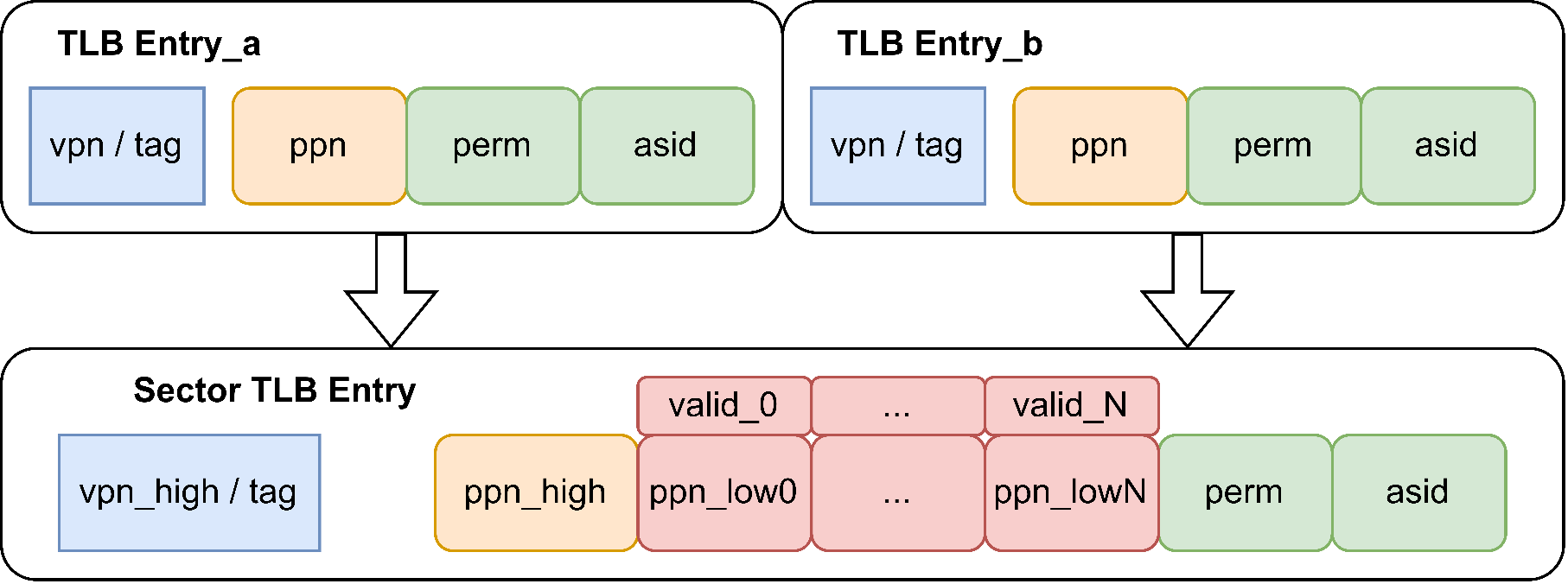
The Kunminghu architecture supports TLB compression, where each compressed TLB entry stores eight consecutive page table entries, as shown in the figure. The theoretical basis for TLB compression is that operating systems, due to mechanisms like buddy allocation, tend to allocate contiguous physical pages to contiguous virtual pages. Although page allocation becomes less ordered over time, this page correlation is common. Thus, multiple contiguous page table entries can be merged into a single TLB entry, effectively increasing TLB capacity.
In other words, for page table entries with the same upper bits of the virtual page number, if the upper bits of the physical page number and the page table attributes are also the same, these entries can be compressed into a single entry for storage, thereby increasing the effective capacity of the TLB. The compressed TLB entry shares the upper bits of the physical page number and the page table attribute bits, while each page table individually retains the lower bits of the physical page number. The valid field indicates whether the page table is valid within the compressed TLB entry, as shown in Table 5.1.8.
Table 5.1.8 shows the comparison before and after compression. The tag before compression is vpn, and the tag after compression is the upper vpnLen - 3 bits of vpn, the lower 3 bits do not need to be saved. In fact, for 8 consecutive page table entries, the i-th entry corresponds to the lower 3 bits of the tag. The upper ppnLen - 3 bits of ppn are the same, and ppn_low saves the lower 3 bits of ppn for each of the 8 page table entries. Valididx indicates the validity of these 8 page table entries; only when valididx(i) is 1 is it valid. pteidx(i) represents the original request corresponding to the i-th entry, i.e., the value of the lower 3 bits of the original request vpn.
An example is given here for illustration. For instance, a certain vpn is 0x0000154, with the lower three bits being 100, i.e., 4. When refilled into the L1 TLB, the 8 page table entries from vpn 0x0000150 to 0x0000157 are all refilled and compressed into 1 entry. For example, the upper bits of ppn for vpn 0x0000154 are PPN0, and the page table attribute bits are PERM0. If for the i-th entry of these 8 page table entries, the upper ppn bits and page table attributes are also PPN0 and PERM0, then valididx(i) is 1, and the lower 3 bits of the i-th page table entry are saved via ppn_low(i). Additionally, pteidx(i) represents the original request corresponding to the i-th entry. Here, the lower three bits of the original request vpn are 4, so pteidx(4) is 1, and all other pteidx(i) are 0.
Additionally, the TLB does not compress query results for large pages (1GB, 2MB) or NAPOT pages. For large pages, each bit of valididx(i) is set to 1 upon return. According to page table query rules, large pages do not actually use ppn_low, so the value of ppn_low can be arbitrary.
| compressed or not | tag | asid | level | ppn | n | perm | valididx | pteidx | ppn_low |
|---|---|---|---|---|---|---|---|---|---|
| No | 27/36 bits | 16 bits | 2 bits | 24/44 bits | 1 bit | Page Table Attributes | Not Saved | Not Saved | Not Saved |
| Yes | 24/33 bits | 16 bits | 2 bits | 21/41 bits | 1 bit | Page Table Attributes | 8 bits | 8 bits | 8×3 bits. |
After TLB compression is implemented, the hit condition of L1 TLB changes from TAG hit to TAG hit (high VPN bits match), while also requiring that valididx(i), indexed by the lower 3 bits of VPN, is valid. PPN is formed by concatenating ppn (high bits) with ppn_low(i).
Note that after adding the H extension, L1TLB entries are divided into four types. The TLB compression mechanism is not enabled for virtualized TLB entries (though TLB compression is still used in the L2TLB). These four types will be described in detail later.
Stores four types of TLB entries
The L1 TLB entries have been modified with the addition of the H extension, as shown in 此图.
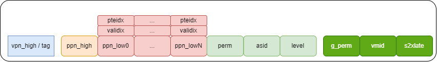
Compared to the original design, g_perm, vmid, s2xlate, pbmt, and g_pbmt have been added. Among them, g_perm is used to store the perm of the second-stage page table, vmid is used to store the vmid of the second-stage page table, s2xlate is used to distinguish the type of TLB entry, and pbmt and g_pbmt respectively store the memory type attributes of the first-stage and second-stage page tables. Depending on s2xlate, the content stored in the TLB entry also differs.
| Type | s2xlate | tag | ppn | n | perm | g_perm | pbmt | g_pbmt | level |
|---|---|---|---|---|---|---|---|---|---|
| noS2xlate | b00 | Virtual page number in non-virtualized mode | Physical page number in non-virtualized mode | NAPOT attribute | Page table entry permissions in non-virtualized mode | Not used | PBMT in non-virtualized mode | Not used | Page table entry level in non-virtualized mode |
| allStage | b11 | Virtual page number of the first-stage page table | Physical page number of the second-stage page table | NAPOT attribute | Perm of the first-stage page table | Perm of the second-stage page table | PBMT of the first stage | PBMT of the second stage | Minimum level in two-stage translation |
| onlyStage1 | b01 | Virtual page number of the first-stage page table | Physical page number of the first-stage page table | NAPOT attribute | Perm of the first-stage page table | Not used | PBMT of the first stage | Not used | Level of the first-stage page table |
| onlyStage2. | b10 | Virtual page number of the second-stage page table | Physical page number of the second-stage page table | NAPOT attribute | Not used | Perm of the second-stage page table | Not used | PBMT of the second stage | Level of the second-stage page table |
Among these, the TLB compression technique is enabled in noS2xlate and onlyStage1, and disabled in other cases. In allStage and onlyS2xlate cases, the L1TLB hit mechanism uses pteidx to calculate the tag and ppn of a valid pte. These two cases also differ during refill. Additionally, asid is valid in noS2xlate, allStage, and onlyStage1; vmid is valid in allStage and onlyStage2; pbmt is valid in noS2xlate, allStage, and onlyStage1; and g_pbmt is valid in allStage and onlyStage2.
TLB refill merges page tables of two stages
With the H extension added to the MMU, the PTW response structure is divided into three parts. The first part, s1, is the original PtwSectorResp, storing the first-stage translation page table. The second part, s2, is HptwResp, storing the second-stage translation page table. The third part is s2xlate, indicating the type of this resp, which can be noS2xlate, allStage, onlyStage1, or onlyStage2, as shown in 此图. Here, PtwSectorEntry is a PtwEntry with TLB compression, with the main difference being the length of the tag and ppn fields.
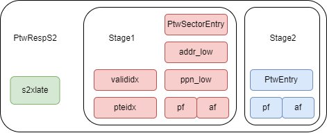
For noS2xlate and onlyStage1 cases, only the s1 result needs to be filled into the TLB entry, with a method similar to the original design, filling the corresponding fields of the returned s1 into the entry's corresponding fields. Note that for noS2xlate, the vmid field is invalid.
For the onlyS2xlate case, we fill the TLB entry with the results of stage 2. Here, due to the need to conform to the TLB compression structure, some special handling is required. First, the asid and perm of this entry are not used, so we don't care what value is filled in at this time. vmid and n are filled with the vmid and n of stage 2. Fill the TLB entry's tag with the stage 2 tag. pteidx is determined by the low sectortlbwidth bits of the stage 2 tag. If stage 2 is a large page, then all valididx of the TLB entry are valid; otherwise, the pteidx of the TLB entry corresponds to a valid valididx. Regarding the filling of ppn, the logic from allStage is reused and will be introduced in the allStage case.
For allStage, the two-stage page tables need to be merged. First, fill in tag, asid, vmid, etc., based on stage 1. Since there is only one level, fill level with the minimum value of stage 1 and stage 2. This is because if a first-stage large page and a second-stage small page exist, querying an address might hit the large page but actually exceed the range of the second-stage page table. For such requests, the tag must also be merged. For example, if the first tag is a first-level page table and the second tag is a second-level page table, we need to concatenate the first-level page number of the first tag and the second-level page number of the second tag (the third-level page number can be directly zero-extended) to obtain the tag of the new page table. Additionally, fill in the perm of stage1 and stage2 as well as s2xlate. Regarding ppn, since we do not save the guest physical address, for the case of a first-stage small page and a second-stage large page, directly storing the ppn of stage2 will cause the physical address calculated upon querying this page table to be incorrect. Therefore, first, based on the level of stage2, concatenate the tag and ppn of stage2. s2ppn is the high-order ppn, and s2ppn_tmp is constructed for calculating the low order. Then fill the high order into the ppn field of the TLB entry, and the low order into the ppn_low field of the TLB entry. For the filled n, the n bit is considered 1 in the following cases:
- When the n bit of stage1 is 1 and stage2 is not a leaf node.
- When the n bit of stage2 is 1 and stage1 is not a leaf node.
- When both the n bits of stage1 and stage2 are 1.
In particular, for an allStage with exceptions, if stage1 raises an exception, the filled level should be written back as s1_level; if stage2 raises an exception:
- If stage1 is a fakePTE, the level should be written back as the maximum value in stage1 and stage2 (indicating a vsatp configuration error).
- If stage1 is a non-leaf node, the level should be written back as s1_level.
- If stage1 is a leaf node, the level should be written back as the minimum value in stage1 and stage2.
Hit detection logic for TLB entries
There are three types of hits used in the L1TLB: TLB query hits, TLB fill hits, and PTW request response hits.
For TLB query hits, parameters such as vmid, hasS2xlate, onlyS2, and onlyS1 have been added. The ASID hit is always true during stage-2 translation. The H extension adds a pteidx hit, which is enabled in the cases of small pages, n bits being 0, and under allStage and onlyS2, to mask the TLB compression mechanism.
For TLB fill hits (wbhit), the input is PtwRespS2. It is necessary to determine the current VPN being compared. If it is a stage-2-only translation, use the high bits of the s2 tag; otherwise, use the s1vpn tag. Then, pad the low sectortlbwidth bits with 0, and compare the VPN against the TLB entry tag. The H extension modifies the wb_valid determination and adds pteidx_hit and s2xlate_hit. If the PTW response is for a stage-2-only translation, wb_valididx is determined by the s2 tag; otherwise, it directly connects to the s1 valididx. The s2xlate hit compares the TLB entry's s2xlate with the PTW response's s2xlate to filter the TLB entry type. The pteidx_hit is for invalidating TLB compression: for stage-2-only translation, it compares the low bits of the s2 tag with the TLB entry's pteidx; for other two-stage translation cases, it compares the TLB entry's pteidx with the s1 pteidx.
For PTW request response hits, this is mainly used to determine, when a PTW response arrives, whether the PTW request sent by the TLB exactly corresponds to that response, or to determine, during a TLB query, whether the PTW response is the PTW result needed for this TLB request. This method is defined in PtwRespS2. Internally, it is divided into three types of hits. For noS2_hit (noS2xlate), only determining whether s1 hits is sufficient. For onlyS2_hit (onlyStage2), only determining whether s2 hits is sufficient. For all_onlyS1_hit (allStage or onlyStage1), the vpnhit determination logic needs to be redesigned; it cannot simply determine s1hit. The level for determining vpn_hit should take the minimum value of s1 and s2, then determine the hit based on the level, and add the hit for vasid (from vsatp) and the hit for vmid.
Support for re-sending PTW to obtain gpaddr after a guest page fault
Since L1 TLB does not preserve the gpaddr in the translation result, when a TLB hits but the queried TLB entry has a guest page fault, the need_gpa special mechanism is required to re-fetch the gpaddr for exception handling. Below are the registers used by the need_gpa mechanism.
| Name | Type | ** function ** |
|---|---|---|
| need_gpa. | Bool | Indicates that there is currently a request acquiring gpaddr |
| need_gpa_robidx | RobPtr | robidx of the request to obtain gpaddr |
| need_gpa_vpn | vpnLen | The vpn of the request to obtain gpaddr |
| need_gpa_gvpn | vpnLen | Stores the gvpn of the obtained gpaddr |
| resp_gpa_refill | Bool | Indicates that the gpaddr of this request has been filled into need_gpa_gvpn |
| resp_s1_level | log2Up(Level+1) | Stores the level of the s1 page table, used for calculating gpaddr |
| resp_s1_isLeaf | Bool | Stores whether s1 is a leaf node |
| resp_s1_isFakePte | Bool | Whether storage s1 is a fake PTE |
| need_clear_need_gpa | Bool | Used to quickly clear need_gpa during PTW fast hit |
need_gpa mechanism
- A TLB query hits a TLB entry, but the entry has a guest page fault. At this point, set need_gpa to valid, fill the requested vpn into need_gpa_vpn, fill the requested robidx into need_gpa_robidx, and initialize resp_gpa_refill to false. Simultaneously send a PTW request, where the getGpa signal is set to true, indicating this request is only for obtaining the gpaddr. If the PTW bypass hits (p_hit_fast), gpaddr-related information can be directly obtained. At this point, set need_clear_need_gpa to clear the need_gpa state in the next cycle, without waiting for the request to be resent.
- After the PTW response, use need_gpa_vpn to determine it is the previously sent request for obtaining gpaddr, and save information such as gvpn, s1_level, s1_isLeaf, s1_isFakePte into registers. If the response is in OnlyStage2, fill the s2 tag of the PTW response into need_gpa_gvpn; otherwise, calculate resp_gpa_gvpn through need_gpa_vpn, and set resp_gpa_refill to valid, indicating that the gvpn of the gpaddr has been obtained. When the previous request re-enters the TLB, this need_gpa_gvpn can be used to calculate the gpaddr and return it. After a request completes the above process, invalidate need_gpa. Here, resp_gpa_refill is still valid, so the refilled gvpn may be used by other TLB requests (as long as it equals need_gpa_vpn). Since getGpa is valid, this PTW response will not refill the TLB.
- When the original request is resent and enters the TLB, since the resp_gpa_refill && need_gpa_vpn_hit condition is met, the miss signal is no longer raised. The TLB uses the cached gpaddr information to return the exception result normally.
During processing, a redirect may occur, causing the entire instruction flow to change. The previous request for obtaining gpaddr will no longer enter the TLB. Therefore, if a redirect occurs, we use the saved need_gpa_robidx to determine whether the registers related to obtaining gpaddr in the TLB need to be invalidated.
To prevent the returned PTW request for obtaining gpaddr from refilling the TLB,
since need_gpa is a register, it cannot prevent refill in the same cycle it is
set. Therefore, the combined logic signal maybe_need_gpa_not_allow_refill is
added to immediately prevent TLB refill in the same cycle that triggers
need_gpa.
Regarding the handling process of obtaining gpaddr after a guest page fault occurs, key points are reiterated here:
-
The mechanism for obtaining gpa can be viewed as a buffer with only 1 entry. When a request incurs a guest page fault, the corresponding need_gpa information is written into this buffer. This continues until the
need_gpa_vpn_hit && resp_gpa_refillcondition is valid, or a flush (itlb) / redirect (dtlb) signal is received to refresh the gpa information. -
need_gpa_vpn_hit refers to: after a guest page fault occurs for a request, the vpn information is written into need_gpa_vpn. If the same vpn queries the TLB again, the need_gpa_vpn_hit signal is raised, indicating that the obtained gpaddr corresponds to the original get_gpa request. If resp_gpa_refill is also high at this time, it means the vpn has already obtained the corresponding gpaddr, which can be returned to the frontend for instruction fetch or backend for memory access to handle the exception.
-
Therefore, for any frontend or memory access request that triggers a GPA, one of the following two conditions must subsequently be satisfied:
- The request triggering gpa can always be resent (the TLB will return a miss for the request until the gpaddr result is obtained).
-
It is necessary to flush or redirect the gpa request by sending a flush or redirect signal to the TLB. Specifically, for all possible requests:
- ITLB fetch request: If a gpf fetch request occurs on the speculative path and incorrect speculation is detected, it will be flushed via the flushPipe signal (including backend redirect or updates from the frontend multi-level branch predictor where later-stage predictor results update earlier-stage predictor results, etc.). For other cases, since the ITLB will return a miss for the request, the frontend ensures the same vpn request is resent.
- DTLB load request: If a gpf load request is on a speculative path and incorrect speculation is detected, it will be flushed via the redirect signal (the relationship between the robidx of the gpf and the robidx of the incoming redirect must be determined). For other cases, since the DTLB will return a miss for the request and simultaneously assert the tlbreplay signal, ensuring the load queue can replay the request.
- DTLB store request: If a gpf store request is on a speculative path and incorrect speculation is detected, it will be flushed via the redirect signal (requires comparing the robidx of the gpf with the robidx of the incoming redirect). For other cases, since the DTLB will return a miss for this request, the backend will reschedule the store instruction to resend the request.
- DTLB prefetch request: The returned GPF signal will be asserted, indicating a GPF occurred for the prefetch request address. However, it will not write to the GPA* series of registers, will not trigger the GPADDR lookup mechanism, and thus requires no further consideration.
- Under the current handling mechanism, it is necessary to ensure that a TLB entry waiting for a gpa during a gpf is not evicted. Here, we simply block TLB refills when waiting for a gpa to prevent replacement. Since a gpf triggers exception handling and subsequent instructions are flushed, blocking refills during gpa waiting does not cause performance issues.
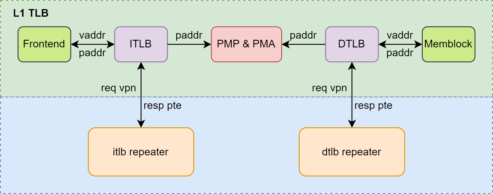
Overall Block Diagram
The overall diagram of the L1 TLB is as described in 此图, including the ITLB and DTLB in the green box. The ITLB receives PTW requests from the Frontend, and the DTLB receives PTW requests from the Memblock. PTW requests from the Frontend include 2 requests from the ICache and 1 request from the IFU. PTW requests from the Memblock include 3 requests from the LoadUnit (AtomicsUnit and VSegmentUnit occupy 1 request channel of the LoadUnit), 1 request from L1 Load Stream & Stride prefetch, 2 requests from the StoreUnit, and 1 request from the SMSPrefetcher.
After obtaining results from ITLB and DTLB queries, PMP and PMA checks are required. Due to the small size of L1 TLB, the backup of PMP and PMA registers is not stored within L1 TLB but in the Frontend or Memblock, providing checks for ITLB and DTLB respectively. Upon a miss in ITLB or DTLB, a query request must be sent to L2 TLB via the repeater.
Interface timing
ITLB and Frontend interface timing
PTW Request from Frontend to ITLB Hits in ITLB
The timing diagram for PTW requests sent by the Frontend to the ITLB when the ITLB hits is shown in 此图.

When a PTW request sent by the Frontend to the ITLB hits in the ITLB, the resp_miss signal remains 0. On the next clock rising edge after req_valid becomes 1, the ITLB sets the resp_valid signal to 1 and returns the physical address translated from the virtual address to the Frontend, along with information on whether a guest page fault, page fault, or access fault occurred. The timing is described as follows:
- Cycle 0: The Frontend sends a PTW request to the ITLB, setting req_valid to 1.
- Cycle 1: ITLB returns the physical address to Frontend, with resp_valid set to 1.
PTW requests sent by the Frontend to the ITLB miss the ITLB.
When a PTW request sent by Frontend to ITLB misses in ITLB, the timing diagram is as shown in 此图.

When a PTW request sent from the Frontend to the ITLB misses in the ITLB, a resp_miss signal will be returned to the Frontend in the next cycle, indicating an ITLB miss. At this point, the requestor channel of this ITLB no longer accepts new PTW requests. The Frontend retransmits the request until the page table in the L2 TLB or memory is queried and returned. (Please note, "The requestor channel of this ITLB no longer accepts new PTW requests" is controlled by the Frontend. That is, whether the Frontend chooses not to resend the missed request or resends other requests, the behavior of the Frontend is transparent to the TLB. If the Frontend chooses to send a new request, the ITLB will directly drop the old request.)
When a PTW request sent from the Frontend to the ITLB misses in the ITLB, a resp_miss signal will be returned to the Frontend in the next cycle, indicating an ITLB miss. At this point, the requestor channel of this ITLB no longer accepts new PTW requests. The Frontend retransmits the request until the page table in the L2 TLB or memory is queried and returned. (Please note, "The requestor channel of this ITLB no longer accepts new PTW requests" is controlled by the Frontend. That is, whether the Frontend chooses not to resend the missed request or resends other requests, the behavior of the Frontend is transparent to the TLB. If the Frontend chooses to send a new request, the ITLB will directly drop the old request.)
When an ITLB miss occurs, a PTW request is sent to the L2 TLB until a result is obtained. The timing interaction between the ITLB and L2 TLB, as well as the return of physical addresses and other information to the Frontend, can be seen in the timing diagram of Figure 4.4 and the following timing description:
- Cycle 0: The Frontend sends a PTW request to the ITLB, setting req_valid to 1.
- Cycle 1: The ITLB query results in a miss, returning resp_miss as 1 and resp_valid as 1 to the Frontend. Simultaneously, the ITLB sends a PTW request to the L2 TLB (specifically to itlbrepeater1) in the same cycle, with ptw_req_valid set to 1.
- Cycle X: The L2 TLB returns a PTW response to the ITLB, including the requested virtual page number, obtained physical page number, page table information, etc., with ptw_resp_valid set to 1. In this cycle, the ITLB has already received the PTW response from the L2 TLB, and ptw_req_valid is set to 0.
- Cycle X+1: ITLB hits at this point, with resp_valid being 1 and resp_miss being 0. ITLB returns the physical address to Frontend along with information on whether an access fault or page fault occurred.
- Cycle X+2: The resp_valid signal returned by the ITLB to the Frontend is set to 0.
DTLB and Memblock interface timing
PTW request sent by Memblock to DTLB hits in DTLB
When a PTW request sent by MemBlock to the DTLB hits, the timing diagram is shown in 此图.
When the PTW request sent by Memblock to the DTLB hits in the DTLB, the resp_miss signal remains 0. On the next clock rising edge after req_valid is set to 1, the DTLB will set the resp_valid signal to 1, simultaneously returning the physical address translated from the virtual address to Memblock, along with information such as whether a page fault or access fault occurred. The timing description is as follows:
- Cycle 0: Memblock sends a PTW request to the DTLB with req_valid set to 1.
- Cycle 1: The DTLB returns the physical address to MemBlock, with resp_valid set to 1.
PTW Request from Memblock to DTLB Misses in DTLB
DTLB and ITLB operate similarly, both supporting non-blocking access (i.e., the TLB internally does not include blocking logic. If the request source remains unchanged, meaning it continuously resends the same request after a miss, it exhibits behavior similar to blocking access. If the request source schedules other different requests to query the TLB after receiving a miss feedback, it exhibits behavior similar to non-blocking access). Unlike frontend instruction fetching, when a PTW request sent by Memblock to DTLB misses in DTLB, it does not block the pipeline. DTLB will return a miss signal and resp_valid to Memblock in the next cycle after req_valid. Upon receiving the miss signal, Memblock can proceed with scheduling and continue querying other requests.
After a DTLB miss occurs during a Memblock access, the DTLB sends a PTW request to the L2 TLB to query the page table from either the L2 TLB or memory. The DTLB forwards the request to the L2 TLB via a Filter, which can merge duplicate requests from the DTLB to the L2 TLB, ensuring no duplicates in the DTLB and improving L2 TLB utilization. The timing diagram for a PTW request from Memblock to the DTLB that misses in the DTLB is shown in 此图, which only depicts the process from the miss to the DTLB sending the PTW request to the L2 TLB.

After the DTLB receives the PTW response from the L2 TLB, it stores the page table entry in the DTLB. When Memblock accesses the DTLB again, a hit occurs, similar to the scenario in 此图. The timing interaction between DTLB and L2 TLB is the same as the ptw_req and ptw_resp parts in 此图.
TLB and tlbRepeater interface timing
TLB sends a PTW request to tlbRepeater
The timing diagram of the PTW request interface from the TLB to the tlbRepeater is shown in 此图.

In the Kunminghu architecture, both ITLB and DTLB employ non-blocking access. On a TLB miss, a PTW request is sent to the L2 TLB, but the pipeline and the PTW channel between the TLB and Repeater are not blocked while waiting for the PTW response. The TLB can continuously send PTW requests to the tlbRepeater, which merges duplicate requests based on their virtual page numbers to avoid resource wastage in the L2 TLB and duplicate entries in the L1 TLB.
As shown in the timing relationship of 此图, in the next cycle after the TLB sends a PTW request to the Repeater, the Repeater continues to forward the PTW request downstream. Since the Repeater has already sent a PTW request for virtual page number vpn1 to the L2 TLB, when it receives another PTW request with the same virtual page number, it will not forward it to the L2 TLB again.
itlbRepeater returns the PTW response to the ITLB.
The interface timing diagram for the itlbRepeater returning PTW responses to the ITLB is shown in 此图.

The sequence description is as follows:
- Cycle X: The itlbRepeater receives the PTW response from the lower-level itlbRepeater via the L2 TLB, with itlbrepeater_ptw_resp_valid asserted high.
- Cycle X+1: The ITLB receives a PTW response from itlbRepeater.
dtlbRepeater Returns PTW Response to DTLB
The timing diagram for the interface where dtlbRepeater returns PTW responses to the DTLB is shown in 此图.

The sequence description is as follows:
- Cycle X: dtlbRepeater receives the PTW response from the L2 TLB passed through the lower-level dtlbRepeater, with dtlbrepeater_ptw_resp_valid high.
- Cycle X+1: dtlbRepeater passes the PTW response to memblock.
- Cycle X+2: The DTLB receives the PTW response.