BPU submodule FTB
Function Overview
The FTB temporarily stores FTB entries, providing more accurate branch instruction locations, types, and other information for subsequent advanced predictors. Within the FTB module, an FTBBank module is responsible for the actual storage of FTB entries, utilizing a multi-port SRAM as memory.
Request reception
At stage 0, the FTB module sends a read request to the internal FTBBank, with the request PC value being the PC passed by s0.
Data read and return
In the next clock cycle after sending the request, which is stage 1 of the predictor, the multi-path signals read from the FTB SRAM will be temporarily stored.
In the next cycle, which is stage 2 of the predictor, the hit signal is generated from the temporary data based on the matching of each way's tag with the actual request tag, and the hit FTB data is selected if a hit occurs. If there is a hit request, the return value is the selected FTB entry and the hit way information; if no hit occurs, the output data is meaningless. The tag corresponds to bits 29 to 10 of the PC.
The data read by the FTBBank module will serve as the prediction result of the FTB module at stage 2. It is passed to the subsequent predictor in the current beat via a combinational logic connection. Additionally, this read result is also latched inside the FTB module and passed again to the subsequent predictor at stage 3 as a prediction result via a combinational logic connection. If the FTB hits, the read hit way number will also be passed as meta information, together with the hit information and cycle count, to the subsequent FTQ module at s3.
Additionally, if there is an "always taken" flag in the FTB entry, the corresponding br_taken_mask in the prediction results of stage 2 is also pulled high within this module.
Data update
Upon receiving an update request, the FTB module determines the update timing based on whether the meta information indicates a hit. If the meta shows a hit, the update is performed immediately in the current cycle. Otherwise, it must wait for 2 cycles to read the existing results from the FTB before proceeding with the update.
Within the FTBBank, when an update request exists, the module's behavior also differs between immediate and deferred updates. For immediate updates, the SRAM write channel in FTBBank is activated, completing the write with the given information. For deferred updates, FTBBank first receives a read request for the update with higher priority than normal prediction read requests, then reads the data in the next cycle, selecting the way encoding that hits the given address and passing it to the external FTB module. If there is no hit in this cycle, the next cycle requires writing to the allocated way. The way selection rule is: if all ways are full, use a replacement algorithm (here, pseudo-LRU, see ICache documentation for details) to select the way to replace; otherwise, select an empty way.
SRAM specifications
Single bank, 512 sets, 4-way, using single-port SRAM, no read hold, with power-on reset.
20-bit tag, 60-bit FTB entry.
The FTB items include:
-
1 bit valid
-
20-bit br slot (4-bit offset, 12-bit lower, 2-bit tarStat, 1-bit sharing, 1-bit valid)
-
28-bit tail slot (4-bit offset, 20-bit lower, 2-bit tarStat, 1-bit sharing, 1-bit valid)
-
4-bit pftAddr
-
1-bit carry
-
1-bit isCall
-
1 bit isRet
-
1-bit isJalr
-
The last bit may be an RVI call
-
2-bit always taken
Overall Block Diagram
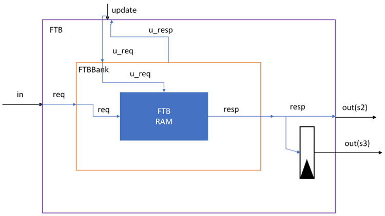
Interface Timing
Result output interface
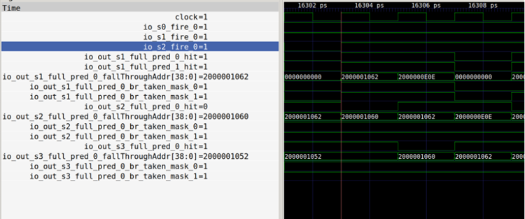
The above diagram shows the interface where the FTB module in the branch predictor outputs prediction results across three consecutive cycles for a request with a fallThrough address of 0x2000001062, at different stages of the branch predictor.
Update interface
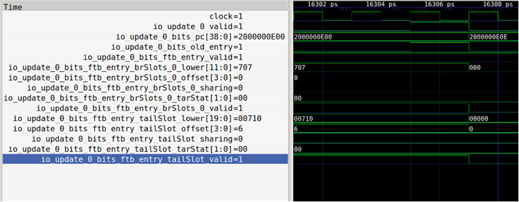
The figure above demonstrates an update operation of the FTB module for address 0x2000000E00, where all update data is transmitted within a single clock cycle.
FTBBank
Interface Timing
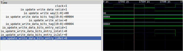
Read data interface

The above figure shows the FTBBank read data interface. FTBBank replies with data one cycle after receiving the request, i.e., the response at 16303ps corresponds to the 0x2000001060 address request at 16301ps.
Update read data interface

Update write data interface
Function Overview
As mentioned above, the FTBBank primarily stores FTB entries and is a simple encapsulation of the SRAM module.
Brief description of FTB entry generation conditions
FTB is the core of BPU. All predictions made by other prediction components of BPU rely on the information provided by FTB. In addition to providing information about branch instructions within the prediction block, FTB also provides the end address of the prediction block. For FTB, the generation strategy of FTB entries is crucial. Based on the original paper 1, the Nanhu architecture combines the ideas from paper 2 to form the current strategy. Let the start address of the FTB entry be 'start' and the end address be 'end'. The specific strategy is as follows:
- The FTB entry is indexed by start, where start is generated in the prediction pipeline. In practice, start generally follows one of the following principles:
- start is the end of the previous prediction block;
- start is the target address of the redirect from outside the BPU;
- The FTB entry can record up to two branch instructions, with the first one always being a conditional branch;
- The end must satisfy one of the three conditions:
- end - start = prediction width
- end is the PC of the third branch instruction within the predicted width range starting from start
- end is the PC of the next instruction following an unconditional jump branch, and it falls within the prediction width range starting from start
Under this training strategy, the same branch instruction may exist in multiple FTB entries.
Similar to the implementation in the paper 1, we only store the lower bits of the end address, while the higher bits are concatenated from the higher bits of the start address. Like AMD's approach 3, we also record an "always taken" bit for conditional branch instructions in the FTB entry. This bit is set to 1 when the conditional branch is first encountered and taken. When this bit is 1, the direction of the conditional branch is always predicted as taken, and its results are not used to train the conditional branch direction predictor. When the conditional branch encounters an execution result of not taken, this bit is set to 0, and thereafter its direction is predicted by the conditional branch direction predictor.
FTB storage structure
FTB entry structure is as follows
| total | valid | brSlot | tailSlot | pftAddr | carry | isCall, isRet, isJalr | last_may_be_rvi_call | strong_bias |
|---|---|---|---|---|---|---|---|---|
| Valid Bit | First branch information | Second branch information | Predict block end address | Whether the high-order bits of the end address carry over | tailSlot branch type | RAS special flag bit | Strong bias | |
| 62 | 1 | 21 | 29 | 4 | 1 | 3 | 1 | 2 |
Composition of FTB slots, each slot corresponds to one branch instruction
| total | valid | offset | lower | tarStat | sharing | isRVC |
|---|---|---|---|---|---|---|
| Valid Bit | Offset relative to the starting PC | Lower bits of target address | Whether the target address high bit carries over | (For tailSlot) Whether a conditional branch is installed | Is it a compressed instruction? | |
| 21/29 | 1 | 4 | 12/20 | 2 | 1 | 1 |
The FTB has a total of 2048 entries, 4-way set-associative, with each entry recording up to 2 branches. The first branch is always a conditional branch, while the second may be any type of branch instruction.
Target address generation logic
For each slot, based on three possible high-bit carry scenarios (carry/borrow/unchanged), select one from (PC high bits +1, PC high bits -1, PC high bits) and concatenate it with the stored target address low bits.
Update process
- Entry generation
1.1 Read necessary information from FTQ:
  - Starting address startAddr
  - The old FTB entry old_entry read during prediction
  - Contains the pre-decoding information pd for all branch instructions
    within the 32Byte FTQ entry
  - The actual jump results cfiIndex of valid instructions within this FTQ
    entry, including whether it jumps and the offset of the jump instruction
    relative to startAddr
  - The jump address (execution result) of the branch instruction (e.g.,
    jump) within this FTQ entry
  - Whether the FTB actually hits during prediction (whether the old FTB
    entry is valid)
  - The misprediction mask for all possible instructions corresponding to
    the FTQ entry
1.2 FTB entry generation logic:
  - Case 1: FTB miss or error exists
    1) Unconditional jump instruction processing:
      - Regardless of whether it is executed, it will always be written to
        the tailSlot of the new FTB entry
      - If the jump instruction in the final FTQ entry is a conditional
        branch, write it to the first brSlot of the new FTB entry and set
        the corresponding always_taken bit to 1
    2) pftAddr settings:
      - When an unconditional jump instruction is present: set the end
        address of the first unconditional jump instruction
      - When there is no unconditional jump instruction: set to startAddr +
        fetch width (32B)
      - Special case: When the start address of a 4-byte-wide unconditional
        jump instruction is at startAddr+30, even if the end address exceeds
        the fetch width range, it is still set as startAddr+32
    3) The carry bit is set simultaneously based on the condition of pftAddr
    4) Set branch type flags:
      - isJalr, isCall, isRet are set according to the type of the first
        unconditional jump instruction
      - Special flag: The last_may_be_rvi_call bit is set if and only if the
        first unconditional jump instruction of 4-byte width starts at
        startAddr+30, and the instruction is of call type.

  - Case 2: FTB hit with no errors
    1) Insert new conditional branch:
      - When there is an available slot: a) tailSlot has an unconditional
        jump: the new conditional branch must be instructionally prior to
        this unconditional jump and is directly inserted into brSlot. b)
        brSlot has a conditional branch: arrange in instruction order,
        ensuring branches in brSlot within the FTB entry are instructionally
        prior to those in tailSlot. c) In the above cases, pftAddr does not
        need modification.
      - When there is no free slot: a) tailSlot has an unconditional jump:
          - The new conditional branch instruction sequence must precede the
            unconditional jump
          - New conditional branch replaces the position of an unconditional
            jump.
          - pftAddr is set according to the PC of the unconditional jump b)
            tailSlot conditional branch: i) The new conditional branch
            instruction sequence is earlier than the existing conditional
            branch instruction sequence in the tailSlot:
            - Arrange the conditional branches in brSlot and new conditional
              branches in instruction order
            - pftAddr is set according to the PC of the original branch in
              tailSlot. ii) The new conditional branch instruction sequence
              is located after all existing branch instructions:
            - No changes occur in the slot
            - Only set pftAddr according to the PC of the new conditional
              branch
    2) Update jalr jump address information:
      - When the tailSlot originally records a jalr (RISC-V's unconditional
        indirect jump instruction)
      - When the jump address changes, modify the corresponding target
        address low bits and high carry information recorded in the
        tailSlot.
    3) Update the always_taken bit:
      - If the always_taken bit is set to 1 and the corresponding
        conditional branch execution result is not taken, pull the
        always_taken bit low
- Write to SRAM
2.1 Write conditions:
- The new FTB entry is completely unchanged, or although the FTB misses but
  the uFTB hits: no need to write.
- New FTB entry has changes and is not a uFTB hit or FTB miss: requires
  writing.
2.2 Write Process: - Case 1: Prediction miss 1) First, perform an FTB read in one cycle to determine the hit condition at this time 2) If hit, write to the corresponding way 3) If it still misses, select a way to write according to the replacement algorithm 4) The entire process requires 3 clock cycles 5) During the process, due to FTB read/write port occupancy, the FTQ must coordinate to avoid issuing new update requests. - Note: Bank partitioning may improve update bandwidth. - Case 2: Prediction hit (including cases where the hit entry contains erroneous information) 1) Directly write to the corresponding way without needing to read again
- The pipeline diagram for writing to SRAM is as follows:
